
Page 112 - Radar Technology Encyclopedia
P. 112
102 CROSSED-FIELD AMPLIFIER CFA, distributed emission [continuous cathode]
transmitter in phased-array radars. When used in an amplifier
chain, the output-stage CFA is often preceded by a medium-
Slow-wave circuit
power traveling-wave tube, which makes it possible to com-
bine the best qualities of both tubes. The traveling-wave tube
provides high gain, and CFA ensures high resultant power
with high efficiency and good phase stability. In Russian Cathode
(sole)
radar literature, the crossed-field amplifier is called a magne- Magnetic field
tron amplifier. Several types of commercial available CFAs
are listed in Table C8. SAL Matching Matching
structure structure
Ref.: Ewell (1981), pp. 37–54; Skolnik (1980), pp. 208–212, (1990),
pp. 4.12–4.14; Brookner (1988), p. 317–324; Leonov (1988), pp. 49–51.
Input Output
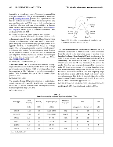
A backward-wave CFA is a crossed-field amplifier in which
Figure C55 Simplified representation of circular-format
electron beam interacts with backward traveling wave as the
CFA (after Ewell, 1981, Fig. 2-12, p. 38).
phase and group velocities of the propagating signal are in the
opposite direction. In backward-wave CFAs, the voltage
required for a given peak current is proportional to frequency,
The distributed-emission [continuous-cathode] CFA is a
and the operating voltage for constant power output depends
crossed-field amplifier in which electron current is obtained
on the frequency amplified; so this device is the voltage-tun-
from the cathode in the interaction space by electron beam
able amplifier. The backward-wave structure was developed
back bombardment (the cathode in CFAs is also known as the
and applied first in comparison with forward-wave CFAs.
sole). A schematic diagram of distributed-emission CFA is
(See AMPLITRON.) SAL
cited in Fig. C56. Electrons start from the cylindrical cathode
Ref. Ewell (1981), p. 38; Skolnik (1990), p. 4.13.
which is coaxial to the RF slow-wave circuit that acts as the
A cathode-driven CFA is a crossed-field amplifier employ- anode. The slow-wave structure is designed in a manner to
ing a cold cathode and started by the RF drive. Such a design make RF signal propagate at a velocity near that of the elec-
permits achievement of about 30 dB of gain in a pulsed mode tron beam to exchange energy from the electron beam to the
in comparison to 10–17 dB that is typical for conventional RF field to produce amplification. The main frequency range
pulsed CFAs. Sometimes this type of CFA is termed a high- for such tubes is from VHF to K band, peak powers up to
u
gain CFA. SAL several megawatts. This device is also called interchangeably
Ref. Skolnik (1980), p. 212. emitting-sole CFA and continuous-cathode CFA. It is the main
The circular-format CFA is the structure of a distributed- type of CFAs used in radar applications. SAL
emission crossed-field amplifier in which the electrons from Ref.: Fink (1975), pp. 9.55–9.60; Skolnik (1980), p. 209; Ewell (1981), p. 37.
the output are isolated from the input forming the nonreen- emitting-sole CFA (see distributed-emission CFA).
trant configuration (Fig. C55). SAL
Ref.: Ewell (1981), p. 37.
Table C8
Some Commercially Available High-Power Pulsed CFAs
Center Maximum
Tube type Peak P o Frequency range Peak Gain
frequency duty cycle
(GHz) (MW) (GHz) Voltage (kV) Current (A) (dB)
1AM10 1.288 1.8 1.225–1.350 0.02 46 50 9.2
QKS1452 2.998 3.0 2.994–3.002 0.0015 47 100 –
SFD222 5.65 1.0 5.4–5.9 0.001 35 60 18
SFD237 5.65 1.0 5.4–5.96 0.01 35 60 13
QKS506 9.05 1.0 8.7–9.4 – 40 45 7
SFD236 16.5 0.1 16–17 0.001 14 23 17
(from Ewell, 1981, p. 55).