
Page 111 - Radar Technology Encyclopedia
P. 111
COVERAGE, radar CROSSED-FIELD AMPLIFIER (CFA) 101
(a)
Figure C52 Typical spaced-based radar coverage. (b)
Tx Rx
Range
Region of
mainlobe -L 0 L
clutter
Blind zones
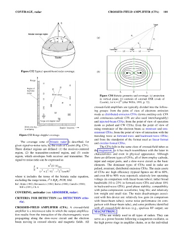
Figure C54 Bistatic geometry and coverage: (a) projection
in vertical plane; (b) contours of constant SNR (ovals of
4
Cassini), for k = L (after Willis, 1991, p. 72).
crossed-field amplifiers are typically divided into the follow-
ing groups: from the point of view of electrons emission
mode as distributed-emission CFAs (terms emitting-sole CFA
and continuous-cathode CFA are also used interchangeably)
Range and doppler clear and injected-beam CFAs; from the point of view of operation
mode as pulsed and CW CFAs; from the point of view of
Blind zone due Doppler frequency
to eclipsing using reentrance of the electron beam as reentrant and non-
reentrant CFAs; from the point of view of interaction with the
Figure C53 Range-doppler coverage. traveling wave as forward-wave and backward-wave CFAs;
and from the standpoint of the format used as linear-format
The coverage zone of bistatic radar is described, for
and circular-format CFAs.
given signal-to-noise ratio, by the ovals of Cassini (Fig. C54).
The CFA falls in the same class of crossed-field tubes as
Three distinct regions are defined: (1) the receiver-centered
the magnetron, so it has much resemblance with the latter in
region, (2) the transmitter-centered region, and (3) cosite
characteristics and even in physical appearance. Although
region, which envelopes both receiver and transmitter. The
there are different types of CFAs, all of them employ cathode,
signal-to-noise ratio can be expressed as
input and output ports, and a slow-wave circuit as the basic
2 elements. The dominant types of CFAs used in radar are
¤
(
S k SN )
min
---- = -------------------------------------------------------------------- pulsed, reentrant, distributed-emission CFAs. The main assets
N 2 2 2 2 2 2
( r + L ¤ ) r L cos q ) of CFAs are: high efficiency (typical figures are 40 to 60%,
–
(
4
where k includes the terms of the bistatic radar equation, and even 80 to 90% were reported); relatively low operating
2
excluding the range terms, r = R R . PCH, SAL voltage (in comparison with linear-beam tubes); rather broad
t r
bandwidth (10 to 25% in forward-wave CFA and about 10%
Ref.: Blake (1982); Hovanessian (1984); Barton (1988); Cantafio (1989);
Willis (1991), Ch. 4. in backward-wave CFA); good phase stability; compatibility
with pulse-compression waveforms; long life; and relatively
COVERING, antiradar (see ABSORBER, radar).
low weight and small size. The main disadvantages associ-
CRITERIA FOR DETECTION (see DETECTION crite- ated with this device are: relatively low gain (in comparison
ria). with linear-beam tubes); worse noise performance (in com-
parison with linear-beam tube), and some problems identified
CROSSED-FIELD AMPLIFIER (CFA). A crossed-field with all crossed-field devices (e.g., spurious RF output; see
amplifier is a microwave tube in which the output amplifica- MAGNETRON).
tion results from the interaction of the electromagnetic wave CFAs are widely used in all types of radars. They can
propagating along the slow-wave circuit and the electron serve as a power booster following a magnetron oscillator, as
beam moving in crossed electric and magnetic fields. All the high-power stage in amplifier chains, or as the individual