Page 106 - Radar Technology Encyclopedia
P. 106

96    CONVOLUTION                                                                COORDINATES, radar


           CONVOLUTION is defined as a function f (t) obtained from
                                                                        y
           two other functions, f (t) and f (t), by the following rule:                       x
                            1
                                   2
                               ¥
                                  1 ò
                                     ×
                                       (
                          ft () =  f t()f t –  t ) t
                                            d
                                       2
                               – ¥
           The typical symbolic notation is
                                                                                                     q sin f
                             ft () f t () f t ()Ä  2
                                =
                                  1
           The concept of convolution is widely used in the theory of
                                                                                        q                    f
           spectral analysis of radar waveforms and digital signal pro-                         q cos f
           cessing.  The convolution theorem states that the Fourier
           transform of the convolution of two functions is the product
                                                                                                            z
           of their individual Fourier transforms. This means that convo-
           lution in the time domain can be carried out by multiplication
                                                                     Figure C45 Spherical coordinate system.
           in the frequency domain. In terms of a signal passing through
           a filter it means that convolution of the input signal and the
           filter impulse response is equivalent to forming the product of             q
           the signal spectrum and the  filter transfer  function.  Digital
           convolution employing fast  Fourier transform  algorithms  is                       Half-power beamwidth
           sometimes termed fast convolution. SAL
           Ref.: Wehner (1987), p. 138.
           COORDINATES, radar. Radar coordinates may refer to
           antenna coordinates or to the radar target coordinates relative
                                                                                                         cos a y
           to the radar system location. Radar-centered coordinate sys-
           tems include rectangular and spherical, as shown in Figs. C44
           and C45.                                                               f

                             altitude, y
                                                                     cos a            Unit circle
                                                                         x
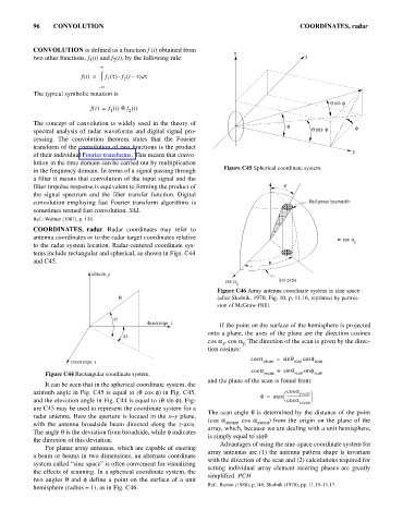
                                                                   Figure C46 Array antenna coordinate system in sine space
                                     R                             (after Skolnik, 1970, Fig. 10, p. 11.16, reprinted by permis-
                                                                   sion of McGraw-Hill).

                                    el
                                              downrange, z
                                                                    If the point on the surface of the hemisphere is projected
                                                                onto a plane, the axes of the plane are the direction cosines
                                       az
                                                                cos a , cos a The direction of the scan is given by the direc-
                                                                           y.
                                                                    x
                                                                tion cosines:
                                                                             cos a   =  sin q  cos f
                      crossrange, x                                              xscan    scan  scan
                                                                             cos a   =  sin  q  sin f
               Figure C44 Rectangular coordinate system.                         yscan    scan  scan
                                                                and the plane of the scan is found from:
               It can be seen that in the spherical coordinate system, the
           azimuth angle in Fig. C45 is equal to (q cos f) in Fig. C45,                æ cos a yscan ö
                                                                                f =  atan  -----------------------
                                                         Fi
           and the elevation angle in Fig. C44 is equal to (q sin f). -                è cos a  ø
                                                           g
                                                                                            xscan
           ure C45 may be used to represent the coordinate system for a
                                                                               i
                                                                The scan angle q s determined by the distance of the point
           radar antenna. Here the aperture is located in the x-y plane,
                                                                (cos a xscan , cos a yscan
                                                                                   ) from the origin on the plane of the
           with the antenna broadside beam directed along the  z-axis.
                                                                array, which, because we are dealing with a unit hemisphere,
           The angle q is the deviation from broadside, while f indicates
                                                                is simply equal to sinq
           the direction of this deviation.
                                                                    Advantages of using the sine-space coordinate system for
               For planar array antennas, which are capable of steering
                                                                array antennas are (1) the antenna pattern shape is invariant
           a beam or beams in two dimensions, an alternate coordinate
                                                                with the direction of the scan and (2) calculations required for
           system called “sine space” is often convenient for visualizing
                                                                setting  individual array  element  steering phases are greatly
           the effects of scanning. In a spherical coordinate system, the
                                                                simplified. PCH
           two angles  q and  f define  a point on  the surface  of a unit
                                                                Ref.: Barton (1988), p.146, Skolnik (1970), pp. 11.15–11.17.
           hemisphere (radius = 1), as in Fig. C46.
   101   102   103   104   105   106   107   108   109   110   111