
Page 105 - Radar Technology Encyclopedia
P. 105
converter, analog-to-digital (ADC) converter, velocity 95
Reference Conversion of parallel digital code into an output current
voltage
consists of switching and summing currents of current gener-
b 1
ators, the number of current generators being equal to the
number of bits of the code. The current of each is doubled
2- 1 comparators from one bit position to another. Usually the current genera-
n N-bit tors are made in the form of transistorized current stabilizers
R Logic binary
b i-1 number (frequently based on multiemitter transistors).
Another method of producing such currents is to use a
resistor circuit (matrix) formed by serial and parallel con-
R
b nected resistors with two values (R, 2R) and switching stages.
i
Elements of the matrix R-2R are produced, usually with thin-
R
film technology, and the switch stages are integrated circuits
Analog
signal (based for example on MOS transistors).
The DAC parameters are analogous to those of ADCs.
Figure C41 Simultaneous analog-to-digital converter. DACs are used mainly to convert digital waveforms produced
by digital waveform generators into analog waveforms, and
Analog
Delay Delay in the interfaces of digital signal processing circuits with ana-
signal T T N-1
summing log data users (e.g., radar displays). IAM
amplifiers Voltage Ref.: IEEE (1993), p. 351; Fink (1982), p. 8.70; Erofeev (1989), p. 493.
N reference
downconverter (see frequency converter).
comparators
A frequency converter is a device that transfers the spectrum
One- One- N One-
bit bit bit of a signal from one region of the frequency band to another
D/A D/A D/A's D/A
without changing the signal structure. Typically it consists of
a mixer and a local oscillator. If the frequency of the output
Delay Delay
(N-1)T (N-2)T signal is less than that at the input, it is termed a downcon-
verter, while in the other direction it is an upconverter. Down-
converters are used in radar receivers to shift the input signal
N-bit digital number
from the carrier frequency to intermediate frequency. Upcon-
Figure C42 Sequential analog-to-digital converter. verters are used in exciters to shift the transmitted waveform
receiver with the threshold amplitude in each of the channels, from intermediate frequency to the carrier frequency. IAM
the number of which is equal to the number of bit positions. Ref.: Druzhinin (1967), p. 368; Fink (1982), p. 14.57; Gassanov (1988),
IAM p. 112.
Ref.: IEEE (1993), p. 36; Skolnik (1970), pp. 5.43–5.49; Gol'denberg (1985), A range converter changes the time delay of the echo signal
p. 6; Demler (1991). into digital code. It contains a generator of reference pulses
Coordinate conversion refers to the computational process which pass through a coincidence circuit to a counter using a
of changing data from one coordinate system (e.g., radar set of triggers. The repetition frequency of the reference
spherical coordinates), to another (e.g., rectangular coordi- pulses is selected to obtain a given accuracy and resolution.
nates) (see COORDINATES, radar). This conversion is typ- The counter moves to the initial zero state with the arrival of a
ically carried out in digital computers. SAL reset pulse at the start of range reading. The counter records
the number of reference pulses that have passed, in binary
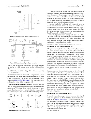
A digital-to-analog converter (DAC) is “a device that con-
representation. The return signals control the counting circuit.
verts an input number sequence into a function of a continu-
If a second target appears, then a second read pulse connects
ous variable.” The input digital code is first converted into a
the counter to a second range cell and so forth. IAM
signal of continuous level, constant within the bounds of one
Ref.: Vasin (1977), p. 214.
time increment, and then is smoothed by a filter (Fig. C43).
upconversion (see frequency converter).
digital analog
DAC Filter
code signal A velocity converter changes doppler frequency into digital
code. The operation of the converter is based on measure-
code V V ments of the doppler frequency in a specific interval of time.
The voltage of the doppler frequency is applied from the out-
put of a mixer to a beat counter through a coincidence circuit
that opens for a fixed measurement time. The value of the
t t t
0 t t t t t 0 t t t t t 0 t t t t t radial velocity is proportional to the number of counts, calcu-
1 2 3 4 5 1 2 3 4 5 1 2 3 4 5
lated with a digital counter. IAM
Figure C43 Digital-to-analog converter. Ref.: Vasin (1977), p. 218.