
Page 103 - Radar Technology Encyclopedia
P. 103
CFAR, log(arithmic) CONTROL 93
Log(arithmic) CFAR uses the output of a logarithmic the median detector and the more general rank-order detector,
receiver as input to a cell-averaging CFAR circuit (similar to or ordered-statistic CFAR. Ranking means arranging the m
Fig. C39), to avoid excessive target suppression from multi- samples from the smallest to the largest and assigning a
ple targets or non-Rayleigh clutter. DKB numerical value equal to the position in the rank order, from 0
to m-1. The target cell amplitude is compared with a thresh-
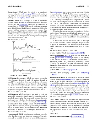
Log-FTC CFAR is a technique in which a logarithmic
old based on the amplitude of the cell of rank X, where
receiver is used, followed by a fast-time-constant (high-pass)
0< X £ m - 1, nd detection is declared if this threshold is
a
video circuit. The log receiver compresses the fluctuations of
exceeded. The largest amplitudes in the reference cells may
strong clutter to the same peak-to-peak amplitude as thermal
be ignored in this process, making this CFAR immune to tar-
noise (Fig. C39), and the FTC circuit removes the DC level to
get suppression from multiple targets.
create a uniform interference output, above which a fixed
When interference samples are correlated over the inte-
threshold can establish the desired false-alarm rate. Log-FTC
gration time of the signal, a modified rank detector known as
CFAR proceeding a visual display can protect against satura-
the modified generalized sign test (MGST) is used, in which
tion and total loss of target detection in regions of strong clut-
the ranker outputs are integrated before being applied to a
ter or other interference. DKB
threshold.
Ref.: Skolnik (1980), pp. 394, 506.
In the median detector, the median value of the target
Voltage
cell, over the n samples gathered during the integration time,
is applied to the threshold. An alternative procedure uses a
Clutter
binary integrator with the second threshold set to (n - 1)/2.
Noise
DKB
Time
Ref.: Skolnik (1970), pp. 8.19 to 8.21; (1980), p. 486.
(a) Input signal
Voltage ordered-statistic CFAR. (see nonparametric CFAR).
Phase-discrimination CFAR refers to the technique in
which a phase-coded waveform is subject to hard limiting
before matched filtering for compression. The technique is
Time sometimes called the coded-pulse anti-clutter system
(b) Log receiver output
Voltage (CPACS). The number of reference cell samples is equal to
the number of subpulses (the pulse-compression ratio). DKB
Threshold Ref.: Skolnik (1990), p. 3.49.
spatial CFAR (see cell-averaging CFAR).
Time
(c) FTC circuit output temporal [time-averaging] CFAR (see clutter-map
CFAR).
Figure C39 Log-FTC CFAR.
Two-parameter CFAR is a technique in which the CFAR
Multiple-carrier-frequency CFAR techniques are applied
constant K (see cell-averaging CFAR) is varied to adapt the
when frequency diversity is used with multiple channels in
system to non-Rayleigh clutter having different spreading of
parallel. Two methods are (1) to sum both the test cell outputs
its probability density function (see clutter (amplitude) dis-
and reference cell outputs several channels before compari-
tribution). Both the mean and standard deviation of the refer-
son of the summed target with the summed threshold, or (2)
ence cell amplitudes are measured, and the threshold setting
to test each channel separately for detection, summing those
is proportional to the product of these two values. In most
outputs that have passed their individual thresholds. DKB
cases, the resulting threshold is so high, when the spread is
Ref.: Nitzberg (1992), pp. 240–245.
significantly greater than that of the Rayleigh distribution,
Multiple-target CFAR techniques are used to avoid the that excessive target suppression (CFAR loss) results. DKB
undesirable suppression of each target by its neighbors within
Ref.: Barton (1988), pp. 92–94.
a multiple-target region. One approach is to censor the stron-
gest one, two, ... cells from the reference region, reducing the CONTRAST, radar. Radar contrast is the degree to which
number of reference cells and increasing the CFAR loss but objects observed by a radar are discriminated from the back-
avoiding effects from multiple targets within the reference ground, making possible their detection, identification, and
region. Another approach, involving somewhat greater CFAR interception with seekers, such as missiles and torpedoes.
loss, is to use the median level of reference cells, rather than Radar contrast is measured by the signal-to-noise ratio. IAM
the average, as the basis for calculating the threshold. DKB Ref.: Popov (1980), p. 188; Mel’nik (1980), p. 19; Finkel’shteyn (1983),
p. 373.
Ref.: Nitzberg (1992), pp. 229–233.
Nonparametric CFAR techniques use statistical properties CONTROL
other than the average and high-order moments of the refer- automatic frequency control (see FREQUENCY).
ence cells to establish the detection threshold. Examples are