Page 98 - Radar Technology Encyclopedia
P. 98

88    clutter, surface                                                                 CODE, CODING


                                                    Specular        In cases where the clutter does not fill the beam, the
                    Interference
                                                      region
                         region    Constant-g  region           equation for volume uses the actual clutter extent in the
                                                                appropriate coordinate, weighted  by the two-way antenna
                 20
                                                                gain. For example, if precipitation is visible over an altitude
                 10
                                                                        0
                                           20 log (r 0 /b 0 )   interval h  to h  in which antenna gain is constant,
                                                                            m
                Reflectivity      s  0 , in dB  10  10 log g    (For data on the volume reflectivity, h , and other properties
                  0
                                                                                   R q
                                                                                                t c
                                                                                   æ
                                                                                        (
                                                                                     c a ö h –
                                                                                               æ
                                                                                             h ) n ö
                                                                                   ------------
                                                                                             0 --------
                                                                              V =
                                                                                          m
                                                                                   è
                                                                                        ø
                                                                               c
                                                                                                 2 ø
                                                                                    L
                                                                                               è
                                                                                     p
                  20
                                                                                               v
                  30
                                                                of  volume clutter, see  atmospheric clutter,  rain clutter,
                                                                snow clutter, and CHAFF). DKB
                  40
                                                                Ref.: Probert-Jones, J. R., “The Radar Equation in Meteorology,” Proc. 9th
                  50
                                                                   Weather Radar Conf., Oct. 23–26, 1961; Doviak, 1984; Barton (1988),
                                                                   pp. 133–137; Morchin (1993), p. 80.
                  60
                  0.1          1           10          100
                               Grazing angle y, in dB
                                                                weather clutter  (see  atmospheric clutter,  rain clutter,
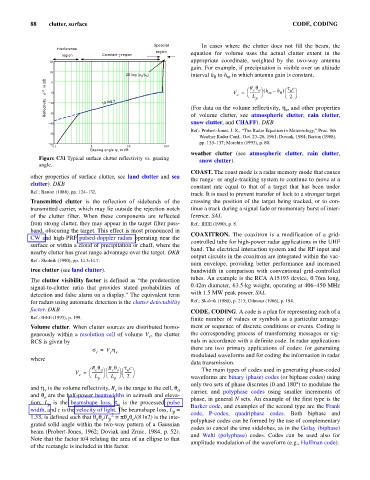
              Figure C31 Typical surface clutter reflectivity vs. grazing
                                                                   snow clutter).
              angle.
                                                                COAST. The coast mode is a radar memory mode that causes
           other properties of surface clutter, see land clutter and sea
                                                                the range- or angle-tracking system to continue to move at a
           clutter). DKB
                                                                constant  rate equal to  that  of  a  target that has been under
           Ref.: Barton (1988), pp. 124–132.
                                                                track. It is used to prevent transfer of lock to a stronger target
           Transmitted clutter  is the reflection of sidebands of the  crossing the position of the target being tracked, or to con-
           transmitted carrier, which may lie outside the rejection notch  tinue a track during a signal fade or momentary burst of inter-
           of the  clutter  filter. When these components  are reflected  ference. SAL
           from strong clutter, they may appear in the target filter pass-  Ref.: IEEE (1990), p. 8.
           band, obscuring the target. This effect is most pronounced in
                                                                COAXITRON. The coaxitron  is a  modification of a grid-
           CW and high-PRF pulsed-doppler radars operating near the
                                                                controlled tube for high-power radar applications in the UHF
           surface or within a cloud of precipitation or chaff, where the
                                                                band. The electrical interaction system and the RF input and
           nearby clutter has great range advantage over the target. DKB
                                                                output circuits in the coaxitron are integrated within the vac-
           Ref.: Skolnik (1990), pp. 14.3-14.7.
                                                                uum envelope, providing better performance and increased
           tree clutter (see land clutter).                     bandwidth in comparison with  conventional grid-controlled
                                                                tubes. An example is the RCA A15193 device, 0.76m long,
           The clutter visibility factor is defined as “the predetection
                                                                0.42m diameter, 63.5-kg weight, operating at 406–450 MHz
           signal-to-clutter ratio  that provides stated probabilities  of
                                                                with 1.5 MW peak power. SAL
           detection and false alarm on a display.” The equivalent term
           for radars using automatic detection is the clutter detectability  Ref.: Skolnik (1980), p. 213; Gilmour (1986), p. 194.
           factor. DKB                                          CODE, CODING. A code is a plan for representing each of a
           Ref.: IEEE (1993), p. 199.                           finite number of values  or symbols  as  a particular arrange-
           Volume clutter. When clutter sources are distributed homo-  ment or sequence of discrete conditions or events. Coding is
           geneously within a resolution cell of volume V , the clutter  the corresponding process of transforming messages or sig-
                                                  c
           RCS is given by                                      nals in accordance with a definite code. In radar applications
                                                                there are two primary applications of codes: for generating
                                s =  V h
                                 c   c v
                                                                modulated waveforms and for coding the information in radar
           where
                                                                data transmission.
                               R q   R q  t c                       The main types of codes used in generating phase-coded
                                 c a ö c e ö n ö
                                         æ
                                    æ
                                          --------
                                     -----------
                          V =  æ ------------  ø L  ø 2 ø
                                    è
                               è
                           c
                                         è
                                L
                                 p     p                        waveforms are binary (phase) codes (or biphase codes) using
                                                                only two sets of phase discretes (0 and 180° to modulate the
                                                                                                    )
           and h  is the volume reflectivity, R is the range to the cell, q a  carrier, and  polyphase codes  using smaller increments of
                v
                                       c
           and q are the half-power beamwidths in azimuth and eleva-  phase, in general N sets. An example of the first type is the
                e
           tion,  L  is  the  beamshape loss,  t is the  processed  pulse  Barker code, and examples of the second type are the Frank
                 p
                                        n
           width, and c is the velocity of light. The beamshape loss, L =  code,  P-codes,  quadriphase codes. Both biphase and
                                                          p
                                      2
           1.33, is defined such that q q/L  = pqq/(8 ln2) is the inte-  polyphase codes can be formed by the use of complementary
                                     p
                                           a e
                                 a e
           grated solid angle within the two-way pattern of a Gaussian
                                                                codes to cancel the time sidelobes, as in the Golay (biphase)
           beam (Probert-Jones, 1962; Doviak and Zrnic, 1984, p. 52).
                                                                and  Welti (polyphase)  codes. Codes can  be used  also for
           Note that the factor p/4 relating the area of an ellipse to that
                                                                amplitude modulation of the waveform (e.g., Huffman code).
           of the rectangle is included in this factor.
   93   94   95   96   97   98   99   100   101   102   103