
Page 94 - Radar Technology Encyclopedia
P. 94
84 clutter, land clutter, rain
A clutter model is a mathematical description of clutter
20
reflectivity and other parameters of clutter, as functions of
10
grazing angle, frequency, polarization, and physical parame-
0
ters of the surface and environment. A complete clutter model
10
will describe the sources affective a given radar, and for each
source the following:
20
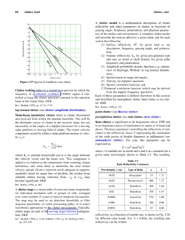
Spectral density in dB 30 windy (1) Surface reflectivity, s , for given land or sea
0
description, frequency, grazing angle, and polariza-
40
tion;
50
v
60 breezy (2) Volume reflectivity, h , for given precipitation type
and rate, or cloud or chaff density, for given radar
70
frequency and polarization;
80
(3) Amplitude probability density function (e.g., param-
light air
90
eters of Rayleigh, Weibull, or log-normal distribu-
100 tion);
0 0.2 0.4 0.6 0.8 1 1.2 1.4 1.6 1.8 2
Velocity in m/s (4) Spatial extent in range and angles;
Figure C27 Spectra of windblown tree clutter. (5) Velocity (or doppler) spectrum;
(6) Spatial correlation function; and
(7)Temporal correlation function (which may be derived
Clutter locking refers to a closed-loop process by which the
from the doppler frequency spectrum).
frequency of a coherent oscillator (COHO) signal is con-
Each of these parameters is defined elsewhere in this section
trolled to keep the clutter spectrum centered in the rejection
and described for atmospheric clutter, land clutter, or sea clut-
band of the clutter filter. DKB
ter. DKB
Ref.: Skolnik (1970), pp. 17.32–17.36.
Ref.: Barton (1988), p. 123.
log-normal clutter (see clutter (amplitude distribution).
point clutter (see discrete clutter).
Main-beam [mainlobe] clutter refers to clutter illuminated
precipitation clutter (see rain clutter, snow clutter).
and received from within the antenna mainlobe. This will be
the dominant source of clutter at the receiver input, but not Rain clutter is significant at all frequencies above VHF and
necessarily at the output of a doppler processor for a moving is an important source of interference to radars at X-band and
radar platform or moving field of clutter. The clutter velocity above. The basic parameter controlling the reflectivity of rain
component caused by relative radar-platform motion at veloc- clutter is the reflectivity factor Z representing the summation
ity v is of the sixth power of droplet diameters in millimeters (see
p
atmospheric clutter). For rain, this parameter can be
q v expressed as
a p
s = ----------- sin a b 6 3
vp 3.34 Z = ar (mm /m )
where r is rainfall rate in mm/h and a and b are constants for a
where q is azimuth beamwidth and a is the angle between given radar wavelength, shown in Table C3. The resulting
a
the velocity vector and the beam axis. This component is
Table C3
added in rss fashion to the components from scanning, clutter
Rain Reflectivity Constants
turbulence, and wind shear to determine the total clutter
velocity spread. Given a rejection notch adequate to suppress Wavelength, l (m) Type of Rain a b
mainlobe clutter by many tens of decibels, the residue from
>0.02 Orographic 31 1.71
sidelobe clutter, having velocities from -v to +v , may
p
p
become significant. DKB >0.02 Thunderstorm 486 1.37
Ref.: Barton (1988), p. 245.
>0.02 Stratiform 200 1.60
A clutter map is a stored table of received clutter magnitudes
0.02 Stratiform 330 1.54
for individual resolution cells or groups of cells, averaged
over some number of scans to remove temporal fluctuations. 0.0086 Stratiform 570 1.00
The map may be used to set detection thresholds or filter
0.006 Stratiform 280 0.80
response parameters, to select processing paths, or to select
waveforms appropriate to the clutter environment. Typically, 0.0032 Stratiform 23 0.60
clutter maps are part of the moving target detector configura-
tion. DKB reflectivity, as a function of rainfall rate, is shown in Fig. C28
>
Ref.: Skolnik (1990), p. 15.65; Schleher (1991), p. 46; Nitzberg (1992), for different radar bands. For l 0.02m, the resulting rain
pp. 233–236. reflectivity can be written