
Page 95 - Radar Technology Encyclopedia
P. 95
clutter, rain clutter, sea 85
5 1.6
p 2 – 18 r – 14 – 1 Table C4
h = ----- K Z ´ 10 = -------- ´ 5.7 ´ 10 m
v 4 4 Typical Clutter Reflectivity Models
l l
2
where |K| = 0.93 is the refractive index factor for water. Source Model Conditions
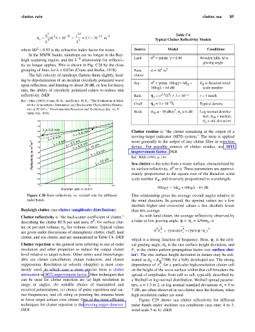
In the MMW bands, raindrops are no longer in the Ray- 0
= 0.06
-4
leigh scattering region, and the l relationship for reflectiv- Land s = g siny, g Wooded hills, y is
grazing angle
ity no longer applies. This is shown in Fig. C28 by the close
4 2
grouping of lines for l < 0.02m (Crane and Burke, 1978). Point s = 10 m
The fall velocity of raindrops flattens them slightly, lead- clutter
ing to depolarization of an incident circularly polarized wave 0
Sea s = g siny, 6K B K is Beaufort wind
10logg = +
B
upon reflection, and limiting to about 20 dB, or less for heavy
10logl - scale number
64 dB
rain, the ability of circularly polarized radars to reduce rain
4
reflectivity. DKB Rain h = (r 1.6 /l ) ´ 3 ´ 10 - 14 r = 3 mm/h
v
Ref.: Atlas (1964); Crane, R. K., and Burke, H. K., “The Evaluation of Mod- - 8
els for Atmospheric Attenuation and Backscatter Characteristic Estima- Chaff h = 3 ´ 10 l Typical density
v
tion at 95 GHz,” Environmental Research and Technology doc. no. P- 2
y
50
3606, Feb. 1978. Birds s = - 30 dBm , s = 6 dB Log-normal distribu-
tion, s = median,
50
20 s = std. deviation
y
30
l= 3.2 mm
40 l= 8.6 mm Clutter residue is “the clutter remaining at the output of a
l= 6 mm l= 3.2 cm more generally to the output of any clutter filter or rejection
50 moving-target indicator (MTI) system.” The term is applied
l= 2 cm
Reflectivity in m 2 /m 3 Reflectivity in m 2 /m 3 100 l= 10 cm device. For possible sources of clutter residue, see MTI
60
l= 5.6 cm
70
l = 23 cm
improvement factor. DKB
80
Ref.: IEEE (1993), p. 199.
90
l= 72 cm
Sea clutter is the echo from a water surface, characterized by
0
110
mately proportional to the square root of the Beaufort wind
120 its surface reflectivity, s or g. These parameters are approxi-
130 scale number K , and inversely proportional to wavelength:
B
140
0.1 1 10 100 10log g = 6K + 10log l 64 dB–
Rainfall rate in mm/h B
Figure C28 Rain reflectivity vs. rainfall rate for different This relationship gives the average overall angles relative to
radar bands. the wind direction. In general, the upwind values are a few
decibels higher and crosswind values a few decibels lower
Rayleigh clutter (see clutter (amplitude) distribution). than this average.
Clutter reflectivity is “the backscatter coefficient of clutter,” As with land clutter, the average reflectivity observed by
0
describing the clutter RCS per unit area, s , for surface clut- a radar at low grazing angle, y < y = l/4ps, is
h
c
ter, or per unit volume, h , for volume clutter. Typical values 0 4 4 4
v
¤
(
are given under discussions of atmospheric clutter, chaff, land s F = ( g sin y) F » ( gy) y y)
c
c
c
clutter, and sea clutter, and are summarized in Table C4. DKB
which is a strong function of frequency. Here, y is the criti-
c
Clutter rejection is the general term referring to use of radar cal grazing angle, s is the rms surface-height deviation, and
h
resolution and other properties to reduce the output clutter F is the clutter pattern-propagation factor (see surface clut-
c
level relative to target echoes. Other terms used interchange- ter). The rms surface height deviation in meters may be esti-
3
ably are clutter cancellation, clutter reduction, and clutter mated as s » K /300, for a fully developed sea. The strong
h
B
suppression. Resolution in velocity (doppler) is most com- dependence of F 4 for a particular high-resolution clutter cell
c
monly used, in which case a more precise term is clutter on the height of the wave surface within that cell broadens the
attenuation or MTI improvement factor. Other techniques that spread of amplitudes from cell to cell, typically described by
can be used for clutter rejection are (a) high resolution in a Weibull or log-normal distribution. Weibull spread parame-
range or angles, (b) suitable choice of transmitted and ters, a = 1.5 to 2, or log-normal standard deviations s = 5 to
y
received polarizations, (c) choice of pulse repetition and car- 7 dB, are often observed in sea clutter near the horizon, when
rier frequencies, and (d) siting or pointing the antenna beam high-resolution radars are used
to favor target echoes over clutter. One of the most efficient Figure C29 shows sea clutter reflectivity for different
techniques for clutter rejection is the moving-target detector. radar bands under medium sea conditions (sea state 4 to 5,
DKB wind scale 5 to 6). DKB