
Page 109 - Radar Technology Encyclopedia
P. 109
COTTON-MOUTON EFFECT coupler, waveguide 99
magnetic field) of the electromagnetic wave through a gyro- is a quarter-wavelength. The band of operating frequencies
tropic medium. This is explained by the separation of the fall- increases with the number of stubs. In practice, the number of
ing wave into two normal linearly polarized waves with stubs never exceeds three, due to the sharp increase in the
different phase speeds. The vector of one of these waves is wave impedance at the edges of the stubs as their number
directed along the external field. increases, and an increase in the active loss.
The Cotton-Mouton effect occurs when radio waves with The hybrid ring coupler usually differs from the stub
frequencies less than 300 MHz are propagated in the iono- coupler in that the length of transmission line between adja-
sphere. IAM cent inputs is increased to three-quarters of the wavelength. In
Ref.: Kravtsov (1983) p. 82; Nikol'skiy (1964) p. 189. the shortwave portion of the microwave band cavity hybrid
ring couplers are used (see Fig. C47), while at larger wave-
COUNTER-COUNTERMEASURES (see ELECTRONIC
lengths the stub coupler in the form of a meander line is
COUNTER-COUNTERMEASURES)
employed.
COUNTERMEASURES (see ELECTRONIC COUN-
TERMEASURES)
Main line
COUPLER, directional. A directional coupler is a multiport
device providing directional coupling of energy. The device
contains a main line and a single or several auxiliary lines Stub Stub l /4
(coupling lines). When one branch of the main line is excited,
a portion of the power is transferred to the other branch of the
main line, and a portion to one of the branches of the coupling Coupling line
line. The second branch of the auxiliary line is not coupled to
the excited branch of the main line, so that no power is trans-
ferred to it.
Figure C47 Two-stub coupler.
One of the main parameters of a directional coupler is the
attenuation, equal to the ratio of the coupled power to the Ring couplers are widely used in waveguide, coaxial, and
power in the forward wave. The directivity is the ratio of the stripline transmission lines. IAM
power in the coupled forward wave to the power in the cou-
Ref.: Gardiol (1984), p. 284; Veselov (1988), p. 61.
pled back wave. The decoupling ratio is the ratio of the power
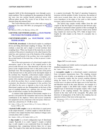
A waveguide coupler is a directional coupler constructed
in the forward wave to the power in the decoupled output of
from waveguide transmission lines. The coupling element
the auxiliary line. Typically, a directional coupler comprises
may either be a set of stubs, or an aperture or slot (Fig. C48).
two transmission lines (waveguide, coaxial, or stripline), con-
In a waveguide coupler that has several coupling elements
nected with coupling elements. Depending upon the method
along the center of the wide wall of the waveguide, the
by which the auxiliary line is excited (in-phase or antiphase
excited wave is in phase with the input wave in the main line,
excitation), the direction of propagation in the auxiliary line
and therefore travels in the same direction. An example of a
will either be the same or opposite to that in the main line.
waveguide coupler is the Bethe hole coupler, which is the
Directional couplers are also distinguished on the basis of the
simplest type of directional waveguide coupler, with a single
type of coupling element (e.g., aperture, slot, or loop). Some
aperture as the coupling element. The opening is usually
types of directional couplers are described below.
located in the wide wall of the waveguide. The phase and
A common radar application of directional couplers is to
direction of propagation of the field in the coupling line are
provide a test point for the transmitter and receiver, after their
opposite to those of the wave in the main line. IAM
combination in the duplexer. Power and receiver sensitivity
test equipment can be connected to this test point, which nor- Ref.: Montgomery (1947), p. 313; Druzhinin (1967), p. 140; Rakov (1970),
vol. 2, p. 258.
mally has a directivity of -30 dB or more. IAM
Ref.: Rakov (1970), p. 255; Gardiol (1984), p. 272; Veselov (1988), p. 57;
Sazonov (1988), p. 106.
A hybrid [3-dB] coupler is one in which there is equal power
Matched
in the output branches. A hybrid coupler in which the electri- absorbing
load
cal fields in the output branches have identical voltages and a
constant phase shift is called a bridge. IAM
Ref.: Sokolov (1984), p. 190; Gardiol (1984), p. 279.
A ring coupler is a closed configuration type of directional
coupler. Typically it is a stub (“square”) coupler or hybrid
ring. A stub coupler is one constructed from two lengths of
transmission line, comprising between them two or more Figure C48 Waveguide (Bethe) coupler.
stubs. The length of the stubs and the distance between them