
Page 121 - Radar Technology Encyclopedia
P. 121
delay line, ultrasonic DEPOLARIZATION, DEPOLARIZER 111
of ultrasonic delay lines depend on the characteristics of the The concept of the delta function is widely used in the theory
transducers used. SAL, IAM ¥
Ref.: Skolnik (1970), p. 20.6; Sloka (1970), p. 178. ò d t – t ) 1=
(
0
A waveguide delay line is an ultrasonic delay line in which – ¥
an acoustic wave propagates with virtually no divergence
of radar signal analysis and is a basic model for the correla-
along the driving surface of a mechanical waveguide. In
tion function of completely random noise. The random pro-
waveguide delay lines the acoustic wave always propagates in
cess that is uncorrelated at any two moments of time is often
a straight line. The most common types of waveguide delay
termed delta-correlated. SAL
lines are strip and wire delay lines. Strip delay lines usually
use shear waves, propagating along the line with multiple Ref.: Levin (1974), p. 522; Urkowitz (1983), p. 6.
reflections from the driving (wide) surfaces. Piezoelectric fin- The DEMATRON is a trade name introduced by Litton
ger transducers are attached to the facing surfaces of a strip Industries for distributed-emission, linear-format, forward-
delay line. The most suitable materials for the delay line itself wave interaction crossed-field amplifier. The dematron (dis-
are magnesium-aluminum, aluminum and iron-nickel alloys. tributed-emission magnetron amplifier) is a microwave
The delay may reach 5 ms, the bandwidth 30% at a frequency amplifier in which the slow-wave circuit and electron current
of 1 MHz, and the typical loss is 6 to 16 dB. are open circuits, and the emitting surface of the cathode is
In wire delay lines, ring- or rod-shaped transducers are distributed along the interaction space. This results in a very
used to excite twisting or longitudinal waves. The wire is usu- high-power magnetron amplifier. The dematron is distin-
ally of an aluminum or iron-nickel alloy. Wire delay lines are guished by the absence of a controlling electrode, so it may be
used to obtain long delays of between 10 and 100 ms, provid- operated with very complex pulsed modulation.
ing a bandwidth of 10 to 20% for signal frequencies in the The basic characteristics of a dematron are its pulse
range 0.5 to 1 MHz, and exhibit typical losses in the range 30 power (up to 1 MW at a duty factor of 0.005), its normalized
to 50 dB. IAM bandwidth (up to 10%), gain (up to 15 dB), and efficiency
Ref.: Skolnik (1970), p. 20.7; Sloka (1970), p. 184; Lukoshkin (1983), (typically near 30%).
p. 247. A dematron has a comparatively simple construction, in
An yttrium-iron-garnet (YIG) delay line is manufactured the form of a long, thin housing with a relatively small cross
from crystals of yttrium iron garnet (3Y O ·5Fe O ). It is section. This makes it well suited to close packing within an
2 3
2 3
used to create delays of long duration, relying on multiple active phased-array antenna. IAM
reflections (see beam-type delay line), and also as delay Ref.: Skolnik (1970), pp. 7.21, 7.6; Ewell (1981), p. 37.
lines with artificial dispersion, which arises in the presence of
DEMODULATION is the process inverse to modulation and
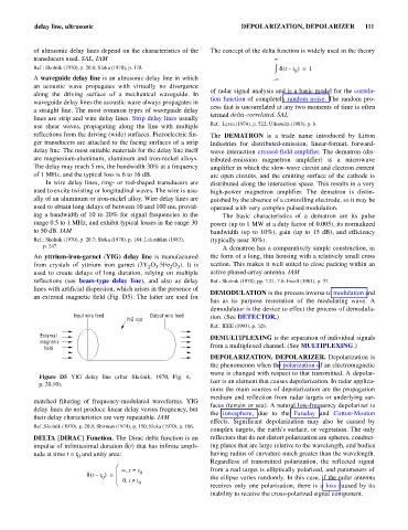
an external magnetic field (Fig. D5). The latter are used for
has as its purpose restoration of the modulating wave. A
demodulator is the device to effect the process of demodula-
Input wire feed Output wire feed tion. (See DETECTOR.)
YIG rod
Ref.: IEEE (1993), p. 326.
External DEMULTIPLEXING is the separation of individual signals
magnetic
field from a multiplexed channel. (See MULTIPLEXING.)
DEPOLARIZATION, DEPOLARIZER. Depolarization is
the phenomenon when the polarization of an electromagnetic
wave is changed with respect to that transmitted. A depolar-
Figure D5 YIG delay line (after Skolnik, 1970, Fig. 6,
izer is an element that causes depolarization. In radar applica-
p. 20.10).
tions the main sources of depolarization are the propagation
medium and reflection from radar targets or underlying sur-
matched filtering of frequency-modulated waveforms. YIG
faces (terrain or sea). A natural low-frequency depolarizer is
delay lines do not produce linear delay versus frequency, but
the ionosphere, due to the Faraday and Cotton-Mouton
their delay characteristics are very repeatable. IAM
effects. Significant depolarization may also be caused by
Ref.:Skolnik (1970), p. 20.9; Shirman (1974), p. 150; Sloka (1970), p. 186.
complex targets, the earth’s surface, or vegetation. The only
DELTA [DIRAC] Function. The Dirac delta function is an reflectors that do not distort polarization are spheres, conduct-
impulse of infinitesimal duration d(t) that has infinite ampli- ing plates that are large relative to the wavelength, and bodies
tude at time t = t and unity area: having radius of curvature much greater than the wavelength.
0
Regardless of transmitted polarization, the reflected signal
æ ¥ t = t from a real target is elliptically polarized, and parameters of
,
d t – t ) = ç 0
(
0 ç the ellipse varies randomly. In this case, if the radar antenna
è 0 t ¹, t 0
receives only one polarization, there is a loss caused by its
inability to receive the cross-polarized signal component.