
Page 125 - Radar Technology Encyclopedia
P. 125
detection, binary detection, coherent 115
whether hypothesis H or H is true. Such a problem typically advantage of the correlation detector is that it is invariant to
1
0
is termed general binary detection, and if s (t) is equal to 0 time delay, while the disadvantage is that two channels and
0
the problem is called simple binary detection. In this sense, complicated integrators using tapped delay lines are required.
binary detection is opposed to multialternative detection, and The filter detector consists of a filter matched to the sin-
circuitry implementing this type of detection is termed a gle-pulse waveform, a coherent integrator, an envelope detec-
binary detector. Sometimes that term is used to denote a tor, and a threshold (Fig. D10).
detector whose input process is binary. SAL
Ref.: DiFranco (1980), p. 263; Barkat (1991), pp. 344–370. Phase Coherent Z 1 1
detector integrator
Blob detection is the term sometimes applied to radars that d 1
)
t
y(t) Matched u(t) = A cos( w + f 2 2
i
0
measure only the location of target in range and angle (i.e., filter u(t) = A sin( w + f Z + Z 2 Threshold
1
t
)
0 i
they recognize a target only as a “blob” located somewhere in d 0
Phase Coherent
space and do not extract any additional information such as detector integrator Z
the target type or RCS). SAL 2
Ref.: Skolnik (1980), p. 434.
Figure D10 Filter detector.
Closed-loop automatic detection is used in an ESM system
where information already learned by the detector is deleted In the correlation-filter detector, the received and refer-
from the flow of new pulses but is used to improve the infor- ence signals pass to a multiplier, the output of which passes
mation about detected emitters (Fig. D8). SAL through a low-pass filter to the envelope detector and thresh-
Ref.: Neri (1991), p. 312. old (Fig. D11). The advantage of the correlation-filter detec-
tor is the absence of the I and Q channels and complicated
Histograms integrators, but it is sensitive to the time delay of the signal.
Cell 1 When this delay is unknown a priori, multichannel detection
is required.
New
emitters
Cell 2 d
Remaining detection y(t) Z 1
pulses Open Multiplier Matched Envelope Threshold
filter
new detector
Cell N tracking d 0
channels u (t)
From ref
front Track
end Updating of parameters file Figure D11 Correlation-filter detector.
Compare
Matching and measurements
pulses Tracking channels Ideal coherent integration requires that the signal phase
not change from pulse to pulse during reception of a pulse
Figure D8 Closed-loop automatic detection (after Neri, 1991,
train. In this case, if there are m pulses in a train, the resultant
Fig. 4.28, p. 312).
amplitude of a received signal is m times that for a single
2
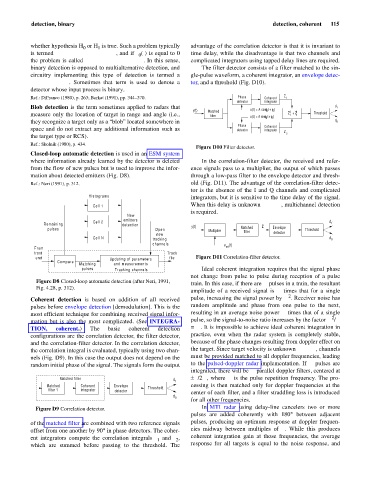
Coherent detection is based on addition of all received pulse, increasing the signal power by m . Receiver noise has
pulses before envelope detection [demodulation]. This is the random amplitude and phase from one pulse to the next,
most efficient technique for combining received signal infor- resulting in an average noise power m times that of a single
2
mation but is also the most complicated. (See INTEGRA- pulse, so the signal-to-noise ratio increases by the factor m /m
TION, coherent.) The basic coherent detection = m. It is impossible to achieve ideal coherent integration in
configurations are the correlation detector, the filter detector, practice, even when the radar system is completely stable,
and the correlation-filter detector. In the correlation detector, because of the phase changes resulting from doppler effect on
the correlation integral is evaluated, typically using two chan- the target. Since target velocity is unknown a priori, channels
nels (Fig. D9). In this case the output does not depend on the must be provided matched to all doppler frequencies, leading
random initial phase of the signal. The signals form the output to the pulsed-doppler radar implementation. If m pulses are
integrated, there will be m parallel doppler filters, centered at
Matched filter d 1 ±f /2m, where f is the pulse repetition frequency. The pro-
r
r
Matched Coherent Envelope Threshold cessing is then matched only for doppler frequencies at the
filter 1 integrator detector center of each filter, and a filter straddling loss is introduced
d 0
for all other frequencies.
Figure D9 Correlation detector. In MTI radar using delay-line cancelers two or more
pulses are added coherently with 180° between adjacent
of the matched filter are combined with two reference signals pulses, producing an optimum response at doppler frequen-
offset from one another by 90° in phase detectors. The coher- cies midway between multiples of f . While this produces
r
ent integrators compute the correlation integrals z and z , coherent integration gain at those frequencies, the average
2
1
which are summed before passing to the threshold. The response for all targets is equal to the noise response, and