
Page 118 - Radar Technology Encyclopedia
P. 118
108 delay line, acoustic-wave delay line, diffraction-grating
The most common delay lines use hypersonic oscilla- frequency of 50 MHz). A typical value for the total loss is 50
10
tions, up to 10 Hz (see ultrasonic delay line, surface- to 60 dB (70 dB for frequencies above 1 GHz). IAM
acoustic-wave delay line). The main advantage of acoustic- Ref.: Skolnik (1970), p. 20.6; Sloka (1970), p. 186.
wave delay lines is that longer delays can be achieved than
A charge-coupled delay line uses a charge-coupled device as
with electrical lines of comparable size, as the wave propa-
the fundamental component. Such a delay line usually com-
gates at sonic speeds. The main disadvantage is that transduc-
prises several (from 2 to 8) multielement registers that have
ers are required to convert the waves, introducing insertion
surface channels, a common timing bus, and a master timing
losses. IAM
generator.
Ref.: Skolnik (1970), p. 20.6; Gassanov (1988), p. 213.
The advantage of a charge-coupled delay line is its com-
An all-pass [time] delay network is an electrical delay line, plete compatibility with integrated semiconductor microcir-
typically a four-terminal lattice network. Ideally it provides cuits. These devices provide a delay up to 60 ms, a voltage
constant gain over its operating band, and the phase shift var- gain between 1.0 and 2.0, and a harmonic coefficient of 3 to
ies with the square of frequency to provide a constant delay 4%. The passband extends from dc to half the repetition fre-
slope. Bridged networks are often used in place of lattice net- quency of the timing pulses and does not exceed 10 MHz.
works for more convenient implementation. Several networks IAM
can be cascaded to increase differential delay. The network Ref.: Gassanov (1988), p. 227.
can be used in linear frequency-modulated waveform genera-
A coaxial cable delay line uses a coaxial transmission line.
tion. SAL
The properties of the delay line are completely determined by
Ref.: Skolnik (1970), p. 20.9.
the length of the cable. The propagation speed of the electro-
An analog delay line uses continuous energy transfer pro- magnetic waves over the coaxial cable is two-thirds of its
cesses. They are implemented with devices in which electro- propagation speed in a vacuum, so that the linear delay is
magnetic waves (electromagnetic delay lines), acoustic waves 0.0005 ms/m. Therefore, in practice it requires that great
(ultrasonic delay lines), and spin waves (YIG delay lines) lengths be used.
propagate. In addition to analog delay lines, wide use is made Typical losses in the line are on the order of 40 dB. Coax-
of discrete-analog delay lines, which rely on the discrete ial cable delay lines are distinguished by a large bandwidth-
nature of charge movement in charge-coupled devices. duration product: 50 to 500 for a conventional cable and 100
Analog and discrete-analog delay lines are used to pro- to 1,000 for a superconducting cable, which limits its basic
cess analog waveforms. The main disadvantage of analog as use to the processing of broadband signals of short duration.
compared with digital delay lines is that their performance is IAM
not stable and repeatable in time, depending on environmental Ref.: Lukoshkin (1983), p. 217.
factors, and they are bulkier and less reliable. IAM
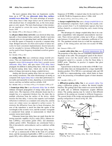
A diffraction-grating delay line is an acoustic delay line
Ref.: Skolnik (1962), p. 119; Sloka (1970), p. 178; Gassanov (1988), p. 227.
using a diffraction grating to achieve the desired transfer
A beam-type delay line is an ultrasonic delay line in which function. The gratings direct the sound wave across the differ-
ordinary divergent propagation of energy takes place in an ent paths and so different frequencies acquire different
elastic wave. The trajectory of the ultrasonic beam may be a delays. The grating spacing may be varied so that different
straight line or a segmented (broken) line, the latter due to portions of the grating are resonant to different frequencies.
multiple reflections from the surface of the device, which The general shape of the wedge and perpendicular diffraction
increase the time delay. A device that supports such multiple grating configuration is shown in Fig. D1. SAL
reflections is referred to as a multiple-entry delay line, and the Ref.: Brookner (1977), p. 138.
waves are volume waves (as opposed to surface waves). To
minimize the diffraction losses due to beam divergence, the
area of the transducer is much less than the square of the
wavelength of the acoustic wave, and the acoustic waveguide
is constructed from metals or monocrystals in which the
acoustic waves travel slowly.
Ultrasonic beam-type delay lines are made from the fol-
lowing materials: sapphire (Al O ), rutile (TiO ), lithium nio-
2
2 3
bate (LiNbO ), iron-sodium garnet (ISG), and aluminum-
3
sodium garnet (ASG). Transducers are constructed from a
film of piezoelectric semiconductor, such as cadmium sulfide
(CdS).
The maximum time delay in beam-type delay lines is
3
5 ´10 ms (a monocrystal of Kbr in the form of a polyhe-
dron), and the maximum bandwidth is 100% (a rod of fused Figure D1 Diffraction-grating delay line (from Brookner,
quartz SiO with a diffused cadmium sulfide transducer, at a 1970, Fig. 30, p. 138).
2