
Page 153 - Radar Technology Encyclopedia
P. 153
display, gas-discharge display, measurement 143
as a pair of deflections, one on each side of a central time base
I-display J-display
representing range (Fig. D52). Both deflections are of equal
amplitude when radar antenna is pointed directly at the target,
Elevation error Range any inequality representing relative pointing error. The time
base (range scale) can be vertical, as in the L-display illustra-
tion, or horizontal.” The L-display is also known as a bearing-
deviation indicator.
Range Signal Ref.: IEEE (1993), p. 707.
amplitude
Azimuth error
Figure D50 G- and H-displays. K-display L-display
achieved. The resolution of gas-discharge matrix displays
2
reaches 25 elements/cm, brightness 40 candles/m , range of
working temperatures 0 to 50°C. Signal intensity Range
Shortcomings of the gas-discharge displays are low sta-
bility of characteristics over the course of the service life,
Range
need for special measures to reduce the delay of the discharge Range
glow, and spread of the luminosity from cell to cell. IAM
Figure D52 K- and L-displays.
Ref.:Fink (1982), p. 23.74; Bystrov (1985), p. 72.
An H-(scope) display is “a B-display modified to include an A liquid crystal display is a passive display based on the use
indication of angle of elevation. The target appears as two of the electro-optical properties of liquid crystals. At low
closely spaced blips approximating a short bright line, the voltages and extremely low power consumption the structure
slope of which is in proportion to the tangent of the angle of of the crystal changes. This is visually fixed as a result of the
target elevation” (Fig. D50). (Obsolete or rare.) great anisotropy of the optical properties. The cell of the liq-
uid crystal display contains two glass plates with semitrans-
Ref.: IEEE (1993), p. 589.
parent electrodes applied to them and a layer of liquid crystal
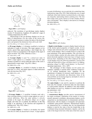
An I-(scope) display is used “in a conical-scan radar, in
between them. Depending on the effect employed the liquid
which a target appears as a complete circle when the radar
crystal displays have the following parameters: reaction time
antenna is pointed at it and in which the radius of the circle is
within the limits 0.03 to 30 ms, relaxation time 0.1 to 1060 ms,
proportional to target range” (Fig. D51). (Rare.) 2
operating voltage 3 to 100V, current density 1 to 10 mA/cm ,
Ref.: IEEE (1993), p. 614.
operating temperatures -10 to +60°C.
A J-(scope) display is a modified A-display in which the The advantages of these displays are low power con-
time base is a circle, and targets appear as radial deflections sumption, capability to operate under conditions of high lev-
from the time base (Fig. D51). els of external background noise, capability for the
Ref.: IEEE (1993), p. 691. manufacture of displays of extremely small thickness (a sin-
I-display J-display gle micron), and practically any dimensions. Some of the
main problems are increasing longevity and depth of colors in
polychromatic displays. IAM
Elevation error Range Ref.: Fink (1982), p. 23.75; Bystrov (1985), p. 108.
The main display is one used by operators to perform the
basic task. For example, in detection radar, the main display
Range Signal is a plan-position indicator. In addition to the main display
amplitude other displays are used (e.g., displays of control and monitor-
Azimuth error
ing subsystems). IAM
Figure D51 I- and J-displays.
Ref.: Popov (1980), p. 269.
A K-(scope) display is “a modified A-display used with a A measurement display provides precise measurement of
lobe-switching antenna, in which a target appears as a pair of the target coordinates. Depending on the number of simulta-
vertical deflections. When the radar antenna is correctly neously measured coordinates, measurement displays can be
pointed at the target, the deflections (blips) are of equal categorized as one-dimensional, two-dimensional, and three-
height, and when not so pointed, the difference in the blip dimensional, with the display in rectangular and panoramic
height is an indication of the direction and magnitude of coordinates (plan-position indicator). Measurement displays
pointing error” (Fig. D52). (Rare.) are characterized by a resolution that for two-dimensional
Ref.: IEEE (1993), p. 696. displays is rated by the value of the dot (bright blip) in the
coordinates being measured (kilometers, degrees), and by the
An L-(scope) display is “similar to a K-display, but signals
scale of the image in the form of the ratio of the limit value of
from the two lobes are placed back to back. A target appears