
Page 148 - Radar Technology Encyclopedia
P. 148
138 DIRECTION FINDER, DIRECTION FINDING discriminator, time-frequency
measurement. The greater angular width of antenna patterns
of this channel makes it possible to remove the ambiguity in Reference t
signal e
the more precise channel. generator
Sometimes the DF uses a remote station (e.g., a satellite) Local
oscillator
separated from a radar to receive jamming signals. In this way Multiplier Detector Filter
the range and azimuth of many jammers may be obtained by y(t) Mixer Subtractor Output
correlating the signals received from several stations.
Multiplier Detector Filter
The term passive DF is sometimes used to stress the pas-
sive nature of DF operation as an ECCM technique, or active
DF to describe the angle measurement capabilities of an Figure D44 Time discriminator (after Tartakovskiy, 1964,
active radar antenna. SAL Fig. 8.2, p. 447).
Ref.: IEEE (1993), p. 1,059; Schleher (1986), p. 96; Neri (1991), pp. 302,
306; Jenkins (1991); Gething (1978). The most prevalent form of time discriminator is the
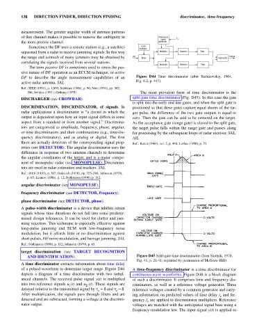
DISCHARGER (see CROWBAR). split-gate time discriminator (Fig. D45). In this case the gate
is split into the early and late gates, and when the split gate is
DISCRIMINATION, DISCRIMINATOR, of signals. In positioned so that these gates capture equal shares of the tar-
radar applications a discriminator is “a circuit in which the get pulse, the difference of the two gate outputs is equal to
output is dependent upon how an input signal differs in some zero. Then the gate can be said to be centered on the target.
aspect from a standard or from another signal.” Discrimina- As the acceptance gate (range gate) is slaved to the split gate,
tors are categorized as amplitude, frequency, phase, angular, the target pulse falls within the range gate and passes along
or time discriminators and their combinations (e.g., time-fre- for processing by the subsequent loops of radar receiver. SAL,
quency discriminators), and as analog or digital. The first AIL
three are actually detectors of the corresponding signal prop- Ref.: Bakut (1964), vol. 2, p. 446; Lothes (1990), p. 55.
erties (see DETECTOR). The angular discriminator uses the
difference in response of two antenna channels to determine
the angular coordinates of the target, and is a major compo-
nent of monopulse radar (see MONOPULSE). Discrimina-
tors are used in radar estimators and trackers. SAL
Ref.: IEEE (1993), p. 367; Dulevich (1978), pp. 323–368; Johnston (1979),
p. 65; Leonov (1986), p. 12; Nathanson (1990), p. 112.
angular discriminator (see MONOPULSE).
frequency discriminator (see DETECTOR, frequency).
phase discriminator (see DETECTOR, phase).
A pulse-width discriminator is a device that inhibits return
signals whose time durations do not fall into some predeter-
mined design tolerances. It can be used for clutter and jam-
ming rejection. This technique is especially effective against
long-pulse jamming and ECM with low-frequency noise
modulation, but it affords little or no discrimination against
short pulses, HF noise modulation, and barrage jamming. SAL
Ref.: Nathanson (1990), p. 112; Johnston (1979), p. 65.
target discrimination (see TARGET RECOGNITION
AND IDENTIFICATION). Figure D45 Split-gate time discriminator (from Skolnik, 1970,
Fig. 41, p. 21.41, reprinted by permission of McGraw-Hill).
A time discriminator extracts information about time delay
of a pulsed waveform to determine target range. Figure D44 A time-frequency discriminator is a time discriminator for
depicts a diagram of a time discriminator with two unbal- continuous-wave waveforms. Figure D46 is a block diagram
anced channels. The received pulse signal y(t) is multiplied of such a discriminator. It comprises time and frequency dis-
into two reference signals u (t) and u (t). These signals are criminators, as well as a reference voltage generator. Three
2
1
delayed relative to the transmitted signal by t + d and t - d. reference voltages created by a common generator and carry-
e
e
After multiplication, the signals pass through filters and are ing information on predicted values of time delay t and fre-
e
detected and are subtracted, forming a voltage at the discrimi- quency f are applied to discriminator multipliers. Reference
e
nator output. voltages are matched with the anticipated signal base using a
frequency-modulation law. The input signal y(t) is applied to