
Page 147 - Radar Technology Encyclopedia
P. 147
diode, Zener (breakdown) DIRECTION FINDER, DIRECTION FINDING 137
A Zener (breakdown) diode is a semiconductor diode in tain number of channels connected to directive antennas to
which avalanche-breakdown current becomes well developed form a monopulse network (Fig. D42).
as the reverse potential is increased beyond the knee of the
current-voltage curve (this occurs at the Zener voltage V ).
z
The typical use is in applications where a source of stable ref-
erence voltage is required. SAL
Ref.: Fink (1975), p. 7.34.
DIPLEX (mode) refers to the mode of operation of two
transmitters alternately at two frequencies within the same
frequency band, using a common antenna. One procedure is
to pulse each transmitter at one-half of the desired pulse repe-
tition frequency, 180° out-of-phase, while another procedure
divides each pulse into two contiguous subpulses, generated
by the two transmitters. The advantage is that higher total
average power is possible because each transmitter is operat-
ing at one-half the total duty cycle of the waveform.
The return signals can be amplified in a common RF
amplifier and separated into two individual channels before
the mixer by means of RF filters, or after a wideband IF
amplifier stage by means of IF filters matched to the band- Figure D42 Amplitude-comparison direction finder from Neri,
width of each pulse. This mode of operation is advantageous 1991, Fig. 4.20, p. 303).
for solid-state transmitters where peak power limitations
more stressing than the average power limitations and their The amplitude-comparison DF is less accurate than the
cost can be reduced if longer pulse duration can be tolerated. phase-comparison DF, but it is used more extensively due to
In some cases when unequal pulse lengths are employed, its lower complexity and cost.
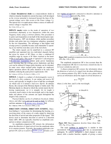
diplex operation allows the pulse duration to be more than A phase-comparison DF extracts the information about
doubled, reducing the peak power requirements. SAL the direction of arrival of a signal from the phase differences
in its antenna patterns (Fig. D43). In this case a phase shift f
Ref.: Johnston (1979), p. 58; Skolnik (1990), p. 3.54.
carries an information about the angle-of-arrival direction a:
DIPOLE. A dipole is a radiator of electromagnetic waves in
the form of a thin conductor. It can radiate and receive RF j = 2pLsin a
----------------------
waves, and typically its length is close to half the wavelength l
(in which case it is termed a half-wave dipole). In antenna where L is the base, and l the wavelength.
is
theory, the concept of the Hertzian dipole is widely used. The
Hertzian dipole is a thread in which the current meets the fol-
lowing requirements: (a) it is straight; (b) its length is
extremely small relative to the wavelength; and (c) the ampli-
tudes and phases of the currents are equal throughout the
length of the conductor.
Practical dipoles can be of cylindrical, biconical, folded,
sleeve, and other types and can be used as feeds for reflector
and lens antennas or as antenna array elements. SAL
Ref.: Johnson (1984), Ch. 4; Sazonov (1988), p. 222.
DIRECTION FINDER, DIRECTION FINDING. Direc-
tion finding is “a procedure for determining the bearing, at a
receiving point, of the source of a radio signal by observing
the direction of arrival and other properties of the signal.” The
device used to determine direction of arrival is a direction
finder (DF). DFs are typically classified as amplitude-com-
parison or phase-comparison types.
Figure D43 Phase-comparison direction finder (from Neri,
An amplitude-comparison DF extracts the information
1991, Fig. 4.23, p. 306).
about the direction of signal arrival from the amplitude ratios
The main problem in application is similar to that
in its antenna patterns. Typically, the modern amplitude-com-
encountered with interferometers and lies in measurement
parison DF, such as is used in an ESM system, includes a cer-
ambiguity. To remove ambiguity, a third channel is intro-
duced, with a smaller baseline, capable of giving a coarse