
Page 142 - Radar Technology Encyclopedia
P. 142
132 device, surface-acoustic-wave (SAW) DICKE FIX
piezoelectric substrate with constant or variable spacings in devices make up a special group of devices based on the
the order of the acoustical wavelength. effect of coherent slowing radiation of electromagnetic waves
SAW devices are used in a frequency band of 1 MHz to 1 by grouped electrons in a homogeneous magnetic field. In
to 3 GHz as delay lines (see DELAY LINE, SAW), filters terms of productivity of interaction with the microwave field,
(see FILTER, SAW), oscillators (see OSCILLATOR, the devices are subdivided into electronic devices with dis-
SAW), and signal-processing devices. tributed and concentrated interaction.
Circuits based on SAWs are quite effective for matched
filtering of phase-coded waveforms, including pseudonoise Vacuum-tube devices
signals. Operation of a SAW convolver, an analog instrument
that performs programmed conversion operations and Electron Nondischarge Gas discharge
matched filtering of pulse-compression waveforms in real
time, is based on nonlinear interaction of acoustic waves. An Electron with with
extended metal plate applied on the surface of a crystal beam dynamic electrostatic
control control
between two interdigital, to which the signals to be convo-
luted are applied, is the output electrode of the convolver.
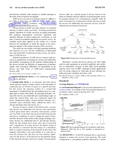
Devices based Gyroresonant O-type M-type Triodes Tetrodes
The small size and weight, with high operating reliability on relativistic
and relatively low cost, and the combination of high-speed streams TWT BWT Magnetron Platinotron TWT BWT
and wide bandwidth in signal-processing circuits, are advan- Klystron O-type O-type M-type M-type
tages of SAW devices.
Industrial production of SAW devices requires high pre- Figure D36 Classification of vacuum-tube devices.
cision of manufacture of topological circuits, and uniformity
and stability of parameters of the substrate. Shortcomings of Electronic vacuum microwave devices are still widely
the devices include the difficulty of suppression of parasitic used in radar equipment as powerful amplifiers and oscilla-
signals with consequent difficulties in repeatability of the tors in transmitters because of their high power-handling
devices and high losses of SAW-based programmable capacity (up to tens of MW), although in many applications
devices. IAM they are being replaced by solid-state devices offering less
Ref.: Fink (1982), p. 9.22; Gassanov (1988), p. 213. bulk and greater reliability and safety. IAM
Ref.: Skolnik (1970), Ch. 7; Popov (1980), p. 490; Andrushko (1981), p. 11;
A transferred-electron device is one employing the Gunn
Zherebtsov (1989), p. 206.
effect in its operation.
DIAGRAM
A (vacuum-)tube device is an electronic and radio device
whose operation requires a high vacuum or the atmosphere of coverage diagram (see COVERAGE).
a particular gas (or mixture of gases) at a specific pressure.
An environmental diagram is the pictorial representation of
For this reason, the operating volume of a vacuum-tube
a clutter model. An example of the environmental diagram for
instrument is insulated from the surrounding space by a gas-
air-defence radar is given in the Fig. D37. SAL
tight glass or metal shell (bulb). In operating principle, vac-
Ref.: Nathanson (1990), p. 293.
uum-tube devices are subdivided into nondischarge types, in
which the current flows only over conductors inside the
device (luminescent lights, vacuum thermal elements, etc.),
electronic types (electronic tubes, cathode-ray tubes, etc.),
and gas-discharge tubes (thyratrons, etc.).
In terms of type of control of the electron flux, vacuum-
tube devices are subdivided into devices with electrostatic
control (grid-control tubes) and those with dynamic control
(see Fig. D36). In the latter, the electrical field formed by the
microwave oscillations is used to change the speed of elec-
tron flux. In terms of the nature of the energy exchange, elec-
tronic devices are subdivided into O- and M-type devices,
which are also termed linear-beam tubes and crossed-field
tubes, respectively. In O-type devices, the kinetic energy of
the electrons is converted into the energy of a microwave Figure D37 Environmental diagram for air-defense radar (from
field as a result of slowing of the electrons by this field. The Nathanson, 1969, Fig. 8.6, p. 294, reprinted by permission of
McGraw-Hill).
magnetic field either is not used entirely or is used only to
focus the electron flux and does not have primary signifi- The DICKE FIX is “an ECCM technique that is specifically
cance for the process. In M-type devices the potential energy designed to protect the receiver from jamming. The usual
of the electrons becomes microwave energy. Gyroresonance configuration is a broadband amplifier followed by a limiter