
Page 138 - Radar Technology Encyclopedia
P. 138
128 detector model detector, phase
since the number of available pulses is usually less than 30, A phase detector produces an output voltage proportional to
this is the appropriate detector. Theoretically, for a fluctuating the phase difference f between the input and reference signals
target, the square-law detector allows simpler analysis and is at a given frequency. A basic phase detector characteristic is
often used. The actual difference in performance is only about the detector response, the dependence of output voltage U out
0.2 dB in any case. SAL on f.
Ref.: Blake (1980), p. 45; Chistyakov (1986), p. 143. Basic phase detector parameters include response slope
S and voltage gain K . The response slope is the maximum
pd
pd
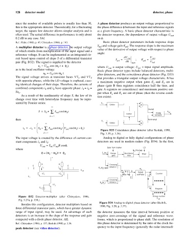
A multiplier detector is a phase detector, the output voltage
value of the derivative of output voltage with respect to phase
of which results from multiplication of the input signal and a
angle:
reference voltage. It can be implemented as an integrated cir-
cuit based upon control of slope S of a differential transistor S pd = dU out ; K pd = U out
-----------
--------------
pair (Fig. D32). The signal is supplied to the detector df max U m1
u = U cos (w t + f), where U = output voltage; U = input signal amplitude.
s
s
s
ms
as is the local oscillator voltage out m1
Basic phase detector types include balanced detectors, multi-
u = U cos w t. plier detectors, and the coincidence phase detector (Fig. D33)
0
h
0
The signal voltage arrives at transistor bases VT and VT 2 that provides a triangular output voltage characteristic. It has
1
with opposite phases, while the LO voltage is cophasal, caus-
a maximum negative output when gates E and E are in
r
s
ing identical changes of their slope. Therefore, the currents of
phase (gate B then registers coincidence half the time, and
combined components i and i have opposite phase: i = i = gate A registers no coincidence) and maximum positive out-
2
2
1
1
Su . put when E and E are out of phase (then the reverse condi-
s
s
r
As a result of the nonlinearity of slope S, the law of its
tion exists).
change over time with heterodyne frequency may be repre-
sented by Fourier series: E s
Limiter A
¥
Inverted
0 å
S = S + S mk cos kw t E out
h
Analog
Inverter subtractor
k = 1
then Noninverted
E
r
¥ Limiter B
æ ö
÷
0 å
i = i – 2 = ç S + S mk cos kw t U cos ( w t + f ) Figure D33 Coincidence phase detector (after Skolnik, 1990,
ç
s
h ÷ ms
s
1
è ø
k = 1 Fig. 3.19, p. 3.36).
The input voltage is created by the difference of current con- Analog-to-digital or fully digital configurations of phase
stant components i and i : detectors are used in modern radars (Fig. D34). In the first,
2
1
U out = S U R cosf,
m1 ms
where Gate from tracker LO
E ( w 1 + - Dw)
s
w
f = - w )t + f. E ( ) Range Bandpass Mixer
(
1 w
s
h
s
s
gate filter
+
R R Crossing
C C
I 1 I E ( w + - Dw) detector
2 s 2 w 3
U out R Q
R-S Gated
VT Counter
2 flip-flop oscillator
VT 1
S R
U 1
Q
Crossing
w
E ( ) detector
R
VT 3 2
C
U 2
Register
Figure D32 Detector-multiplier (after Chistyakov, 1986, Binary number
E out
Fig. 5.27a, p. 158,).
Figure D34 Analog-to-digital phase detector (after Skolnik,
Besides this configuration, detector-multipliers based on
1990, Fig. 3.20, p. 3.37).
three differential transistor pairs, which have greater dynamic
range of input signal, may be used. An advantage of such the detector measures the time interval between positive or
detectors is an increase in the slope of the response and gain negative zero-crossings of the signal and reference wave-
compared with a diode phase detector. AIL forms, which is proportional to phase shift. The resolution of
Ref.: Chistyakov (1986), p. 157; Skolnik (1990), p. 3.36. this phase detector is determined by the ratio of the clock fre-
quency to the input frequency (generally the radar intermedi-
peak detector (see video detector).