
Page 135 - Radar Technology Encyclopedia
P. 135
detection, single-scan [burst] detector, amplitude-phase 125
tion. It is sometimes called single-burst detection, or (when quency, phase, or amplitude-phase detectors; all are nonlinear
only one pulse per beam is used) single-hit, single-pulse or devices.
single-sample detection. SAL In the amplitude detector, all phase information is
destroyed, and this method is used in noncoherent radars
sliding-window detection (see moving-window detection).
where phase information is not used for signal processing.
stationary-target detection (see TARGET RECOGNI- The difference between the amplitude-phase (or phase-
TION AND IDENTIFICATION). sensitive) detectors and phase detectors is that in the former
both amplitude and phase information are present at the out-
Threshold detection is based on establishing a threshold
put, while only phase information is present in the latter case.
level at the output of the receiver and making the decision
This also distinguishes them from mixers, where amplitude,
that a signal is present if the receiver output exceeds that
frequency, and phase information is present (doppler fre-
threshold level. It is the general term defining detection using
quency is not taken into consideration in this classification).
a threshold to make a decision whether the signal is present or
The phase detector is important in coherent radars that use
absent. SAL
signal phase in subsequent processing.
Ref.: Nathanson (1990), p. 124.
Based on the type of nonlinear elements used, detectors
Trimmed-mean detection discards the smallest and the larg- are classified as vacuum-tube or solid-state (crystal) detec-
est of the n pulses before taking the mean and performs as a tors. The latter are most widely used in modern radars. AIL,
mean detector. It can improve the performance of mean detec- SAL
tion but needs to perform the ranking of the pulses, some- Ref.: Druzhinin (1967), p. 382; Blake (1980), p. 45; Chistyakov (1986),
times a rather difficult task to implement in practice. SAL p. 138; Skolnik (1990), p. 3.32.
Ref.: Skolnik (1980), p. 486.
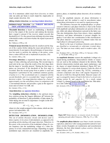
An amplitude detector extracts the amplitude (voltage) of a
Two-stage detection is sequential detection that uses two signal having modulation. Semiconductor diodes or transis-
stages of data collecting and processing. The second stage is tors are used as the nonlinear element in the detector. Main
used only in the case when the results of the first stage show detector characteristics include gain, input conductance, and
that the target is “possibly present.” During the first stage, n the degree of signal distortion introduced. Figure D27 pro-
pulses are processed. If the threshold of the first stage is vides a diagram of a series diode detector. Under the effect of
exceeded, then the second group from m pulses is used and input voltage, pulses of current, Fig. D27(b), containing a
integration is performed for the combined common quantity constant component and those with angular frequencies w,
of pulses m + n. The accumulated sum is compared with the 2w, and so forth flow through the diode. Detector output volt-
second threshold, and it is exceeded then “target is present” age is averaged by means of load in the form of a circuit com-
decision is taken. Two-stage detection reduces by a factor of prising resistor R and capacitor C . As a result, output
n
n
approximately two the surveillance times in comparison with voltage U changes based on the modulation law. This detec-
W
a conventional detector and provides a gain in the signal-to- tor is also called an envelope detector. AIL
noise ratio of about 3 to 6 dB. AIL Ref.: Schwartz (1959), p. 107; Chistyakov (1986), p. 140.
Ref.: Skolnik (1970), p. 15.24. I I out
visual detection (see operator detection).
I R
The weighting (detection) criterion is the optimum detec- C n n U W
tion criterion giving the biggest difference DP between the
U in
probability of detection P and probability of false alarm P , t
fa
d
while taking into account its importance (weight) in the deci- U in U W
sion-making process: (a)
DP = P – hP = max
d fa
where h is the weight assigned to false alarms, which are dan- t
gerous and undesirable. AIL (b)
t
Ref.: Druzhinin (1967), p. 531.
DETECTOR [DEMODULATION, DEMODULATOR]. Figure D27 Diode detector: (a) detector circuit; (b) detector
This set of articles discusses circuits and devices used to operating principle (after Chistyakov, 1986, Fig. 5.2, p. 140).
detect signals, in the sense of demodulation, as opposed to the
preceding articles dealing with target detection. Detection, in The amplitude-phase detector uses linear circuits (resistors,
this sense, is the conversion of the modulated voltage of a car- capacitors, inductors) with varying parameters instead of non-
rier frequency into the modulating voltage of a video fre- linear circuits. Examples are synchronous and asynchronous
quency to reveal a transmitted message. Depending on signal detectors, the first often termed a phase-sensitive [discrimi-
modulation type, detectors are classified as amplitude, fre- nating] detector. SAL
Ref.: Druzhinin (1967), p. 381; Skolnik (1990), p. 3.32.