Page 137 - Radar Technology Encyclopedia
P. 137

detector, frequency                                                                 detector model  127


               The  frequency detector response is the dependence of  These frequency detectors require preliminary amplitude
           output voltage U out  out on signal frequency f given constant  limiting of the signal.  Therefore, changes  are  sometimes
           input voltage amplitude. An important detector parameter is  introduced into detector circuits so they will acquire the addi-
           response slope:                                      tional properties of a limiter. AIL
                                  dU out                        Ref.: Chistyakov (1986), pp. 161–168.
                              S =  --------------
                              d
                                   df
                                       f =  f 0                 linear detector (see detector model).
           where   f  = carrier frequency.                      A lin(ear)-log(arithmic) detector is one in which the output
                  0
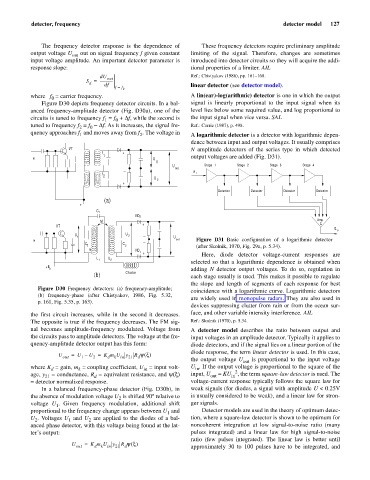
               Figure D30 depicts frequency detector circuits. In a bal-  signal is linearly proportional to the input signal  when  its
           anced frequency-amplitude detector (Fig. D30a), one of the  level lies below some required value, and log proportional to
           circuits is tuned to frequency f  = f  + Df, while the second is  the input signal when vice versa. SAL
                                       0
                                    1
           tuned to frequency f  = f  - Df. As it increases, the signal fre-  Ref.: Currie (1987), p. 498.
                           2
                               0
           quency approaches f  and moves away from f . The voltage in  A logarithmic detector is a detector with logarithmic depen-
                                               2
                           1
                                                                dence between input and output voltages. It usually comprises
                        VT                                      N amplitude detectors of the  series type in which  detected
                                   f      +
                                   1
            in                                      U           output voltages are added (Fig. D31).
                                                     1
                                                          U          Stage 1   Stage 2    Stage 3    Stage 4
                                                           out
                                   f                             E i
                                   2
                                                    U
                                                     2
                                          +
                                                                         Detector   Detector   Detector  Detector
                                   (a)
                           +
                                 C r
                                              VD 2
                                  M                                                                       Amp
                                                                                                           S
                    VT                          +
                                                                                                               E
                                                                                                                o
                          U                U  2
                          1                               U
            in                                             out    Figure D31  Basic configuration of a logarithmic detector
                             C            C
                              1           2                       (after Skolnik, 1970, Fig. 29a, p. 5.34).
                              m               VD
                                               1
                                                                    Here, diode detector  voltage-current  responses are
                                                 +
                                 L   L
                                  1   2
                                                                selected so that a logarithmic dependence is obtained when
                +E
                 k                                              adding  N detector output voltages. To do so, regulation in
                                           Choke
                                (b)                             each stage usually is used. This makes it possible to regulate
                                                                the slope  and length of segments  of each response for best
              Figure D30  Frequency detectors: (a) frequency-amplitude;
                                                                coincidence with a logarithmic curve. Logarithmic detectors
              (b) frequency-phase (after Chistyakov, 1986, Fig.  5.32,
                                                                are widely used in monopulse radars. They are also used in
              p. 161, Fig. 5.35, p. 163).
                                                                devices suppressing clutter from rain or from the ocean sur-
           the first circuit increases, while in the second it decreases.  face, and other variable intensity interference. AIL
           The opposite is true if the frequency decreases. The FM sig-  Ref.: Skolnik (1970), p. 5.34.
           nal becomes amplitude-frequency  modulated. Voltage from  A  detector model  describes the ratio between output and
           the circuits pass to amplitude detectors. The voltage at the fre-  input voltages in an amplitude detector. Typically it applies to
           quency-amplitude detector output has this form:      diode detectors, and if the signal lies on a linear portion of the
                                                                diode response, the term linear detector is used. In this case,
                    U  out  =  U –  U =  K m U in  y 21  R yx()
                                2
                            1
                                     d
                                       k
                                               d
                                                                the output voltage U out  is  proportional to the  input voltage
           where K  = gain, m  = coupling coefficient, U  = input volt-  U . If the output voltage is proportional to the square of the
                                                                  in
                                                in
                           k
                  d
           age, y  = conductance, R  = equivalent resistance, and y(x) input, U out  = KU in 2 , the term square-law detector is used. The
                21
                                d
           = detector normalized response.                      voltage-current response typically follows the square law for
               In  a balanced frequency-phase detector (Fig. D30b), in  weak signals (for diodes, a signal with amplitude U < 0.25V
           the absence of modulation voltage U  is shifted 90° relative to  is usually considered to be weak), and a linear law for stron-
                                        2
           voltage  U . Given frequency modulation,  additional shift  ger signals.
                    1
           proportional to the frequency change appears between U  and  Detector models are used in the theory of optimum detec-
                                                        1
           U . Voltages U  and U  are applied to the diodes of a bal-  tion, where a square-law detector is shown to be optimum for
             2
                        1
                              2
           anced phase detector, with this voltage being found at the lat-  noncoherent integration at low signal-to-noise  ratio  (many
           ter’s output:                                        pulses  integrated)  and a linear law  for  high signal-to-noise
                                                                ratio (few pulses integrated). The linear law is better  until
                         U out  =  K m U in  y 21  R yx()       approximately 30 to 100 pulses have to be integrated, and
                                d
                                  k
                                          d
   132   133   134   135   136   137   138   139   140   141   142