
Page 136 - Radar Technology Encyclopedia
P. 136
126 detector, asynchronous detector, frequency
An asynchronous detector is an amplitude-phase detector
Input Balanced Low-pass Output
not using synchronization of phases of input and reference mixer filter
signals. In the simplest case, an asynchronous detector is a f , f 0
0
diode amplitude detector, to the input of which two signals
f , f
are applied: the received signal from the IF amplifier and the 0 0
local oscillator signal. AIL Reference
Ref.: Druzhinin (1967), p. 382. oscillator
The back bias detector performs much the same function as
instantaneous automatic gain control, except that it operates
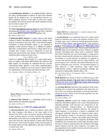
Figure D29 Basic configuration of a coherent detector (after
at the diode detector instead of the IF amplifier. SAL
Skolnik, 1980, Fig. 10.4, p. 385).
Ref.: Johnston (1991), p. 58.
A crystal detector is an amplitude detector in which crystal
A balanced(-diode) detector is a phase detector, the output
diodes or transistors are used as the nonlinear element. Crys-
voltage of which is the difference between the voltages in the
tal diode types used in detectors include germanium diodes,
loads of each detector arm (Fig. D28). At the detector output,
Schottky-barrier diodes, and tunnel diodes with junctions
oscillations of phase-modulated signal U in are supplied in based on the Josephson effect. Bipolar and field-effect tran-
antiphase, while reference voltage U is supplied in cophase. sistors usually may also be used. When bipolar transistors are
2
Therefore, if signal phase and reference voltage phase do not
used, the detectors are referred to as base, collector, or emitter
coincide, then voltages varying in amplitude act upon the
detectors depending upon where load is connected. When
diodes and signal polarity may change. The expression for the
field-effect transistors are used, load usually is connected to
amplitude-phase response has this form:
the drain circuits and the detectors are called drain detectors.
U out = 2K U cosf
d in
where K = amplitude detector gain; U = input signal ampli- Advantages of crystal elements in detectors as opposed to
in
d
vacuum-tube elements include small size, high reliability, and
=
tude; f angle of the phase shift between the reference and
good response curve. Schottky and tunnel diode detectors are
input signals. An advantage of a balanced detector over the
used in millimeter-wave receivers. An important property of
conventional phase detector is the better amplitude-phase
these detectors is high sensitivity, large signal band-
response curve. Amplifiers are used instead of diodes if there
width-duration product, sufficient mechanical strength, and
is a requirement to increase gain and input resistance. AIL
resistance to unfavorable climatic effects. AIL
Ref.: Chistyakov (1986), p. 155; Skolnik (1990), p. 3.36.
Ref.: Van Voorhis (1948), p. 197; Chistyakov (1986), p. 144; Rozonov
(1989), pp. 29, 112–141.
+
U R C Diode detectors are based on diodes of different types as the
1
U main rectifying element. The main types of diode detectors
U in out
are balanced diode detector, Schottky-barrier diode detector,
U R C
1 and tunnel diode detector. SAL
+
An envelope detector reproduces the amplitude of the carrier
envelope and so extracts the modulation and rejects the car-
rier. In this case all phase information is destroyed and subse-
U 2
Figure D28 Balanced phase detector (after Chistyakov, 1986, quent processing is based on the envelope amplitude. See also
Fig. 5.22,. 155). amplitude detector. SAL
Ref.: Skolnik (1980), p. 382.
A balanced bias detector is a controlling circuit used in
A frequency detector extracts the voltage representing the
radar systems for anticlutter purposes.
frequency modulation applied to the carrier. Depending upon
Ref.: Johnston (1979), p. 58.
operating principle, such detectors are categorized as fre-
boxcar detector (see CIRCUIT, sample-and-hold). quency-amplitude, frequency-phase, or frequency-pulse
detectors. In frequency-amplitude detectors, the change in
A coherent detector uses a reference-oscillator signal with
signal frequency is converted to a change in amplitude with
the same frequency and phase as the input signal to be
subsequent amplitude detection. In frequency-phase detec-
detected (Fig. D29). It does not destroy the phase information
tors, the frequency change is converted into a change in phase
as does envelope detector, nor does it destroy the amplitude
shift between the two voltages with further phase detection.
information as does the zero-crossing detector. The signal-to-
In frequency-pulse detectors, the frequency-modulated (FM)
noise ratio from the coherent detector is better than from the
oscillations are converted into a pulse train, the pulse repeti-
previous two, but because the phase of the received signal is
tion rate of which is proportional to the deviation of the input
not usually known in radar applications, this type of detector
signal frequency from the carrier frequency. An output volt-
is seldom used. SAL
age proportional to the number of pulses per unit time may be
Ref.: Skolnik (1980), p. 385.
formed using a pulse counter.