
Page 143 - Radar Technology Encyclopedia
P. 143
DICKE FIX diode, avalanche transit-time (ATT) 133
and then an IF amplifier of optimum radar signal bandwidth.” DIODE, microwave. A microwave diode is a two-electrode
SAL microwave device. In its solid-state form it uses an electrical
Ref.: IEEE (1990), p. 10; Johnston (1979), p. 58. junction as a fundamental element of its structure. The junc-
tion in this type of diode is formed at the place of contact
DIELECTRIC. A dielectric is “a material that can withstand
between metal and semiconductor or at the boundary between
high electric stress without appreciable conduction.” The
two conductors with different types of conductivity (electron
dielectric properties of a material are characterized by several
conductors are n-type and hole conductors are p-type). These
parameters, basic to which is the dielectric constant. Dielec-
junctions are characterized by the existence of a potential bar-
trics are represented primarily by insulators with low conduc-
rier that permits current flow in only one direction. The elec-
tance, but semiconductors also have dielectric properties. The
trical junction may arise even in the absence of a statistical p-
only perfect dielectric, with zero conductance, is an absolute
n junction (the Gunn effect). The majority of diodes are made
vacuum. SAL
with germanium (Ge), silicon (Si), or gallium arsenide
The (relative) dielectric constant is “the ratio of the force (GaAs) by introducing into a monocrystal a precise quantity
between electrical charges in vacuum to the force between of impurities from other elements, thus altering the conduc-
them in a specified medium” (a dimensionless constant, usu- tivity. The choice of the semiconductor material, the type of
ally denoted by e). The word “relative” is usually omitted but impurity and their distribution is determined by the purpose
r
is understood. In microwave components it can be considered of the diode and the range of its application. Depending on
as the ratio by which the capacitance is increased when a the application, microwave diodes are typically categorized
given dielectric material replaces a vacuum between two elec- as belonging to one of the following classes: detector, mixer,
trodes. Other terms that are used interchangeably are relative oscillator, multiplier, and switching diodes. Each class of
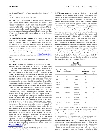
permittivity or relative capacivity (see PERMITTIVITY). diode generally includes diodes of various types. Table D6
SAL shows the main function and limiting conditions of applica-
Ref.: Fink (1982), p. 1.10; Jordan (1985), pp. 4.12, 33.5; Popov (1980), tion for various types of microwave diodes.
p. 118.
Table D6
DIFFRACTION is “the deviation of the direction of energy Microwave Diodes
flow of a wave when it passes an obstacle, a restricted aper-
ture, or other inhomogeneities in the medium.” It appears as a Max.
modification of the free-space electromagnetic field resulting Type of Negative Application Max. average
diode conductivity frequency power
from the interaction of the radar wave with surfaces in the
? (GHz) (W)
vicinity of the direct path or obstacles in the direct path. The
amount of diffraction is a function of the wavelength of the PN no detector 20 0.1
radiation relative to the size of the interfering object; the
PIN no mixer 20 10
larger this ratio, the larger the diffraction effect. In consider-
ing radar propagation, there are two basic types of diffraction: Schottky no detector, 300 0.1
smooth-sphere diffraction, when waves are diffracted around barrier mixer
the curved earth, and knife-edge diffraction, which occurs in tunnel statistical oscillator 100 10 - 5
the presence of obstacles projecting above the surface. At (amplifier)
microwave frequencies, smooth sphere diffraction into the
Gunn dynamic oscillator 150 1
shadow zone is negligible, but very low frequency (VLF);
(amplifier)
that is, long wavelength, electromagnetic waves are diffracted
around the curved earth and provide the basis for worldwide IMPATT dynamic oscillator 200 5
communications. Knife-edge diffraction occurs in the pres- (amplifier)
ence of an obstacle such as a hill, tower, or building, which TRAP- dynamic oscillator 10 10
project above the smooth-earth radar horizon in the path of ATT (amplifier)
the electromagnetic wave. Behind the mask angle, due to
wave-diffraction effects, the radar propagation factor drops to The construction of the diode is determined by the oper-
zero more slowly than for the smooth sphere case, enabling ating band and the means by which it is incorporated into the
some radars to detect targets in the masked, or shadow, waveguide. There are socketed and coaxial housed diodes and
region. As with smooth-sphere diffraction, this effect is more also unhoused diodes. IAM
pronounced for low-frequency radars, but it has been Ref.: Fink (1982), pp. 7.38–7.42; Jordan (1985), p. 18.12; Gorbachev (1968),
exploited at microwave frequencies by communications sys- p. 5; Gassanov (1988), p. 72; Andrushko (1981), pp. 102, 120.
tems. The main radar types that take advantage of diffraction An avalanche transit-time (ATT) diode has negative con-
effects are high-frequency surface-wave radars. (See also ductivity in the avalanche breakdown mode. A layer of ava-
PROPAGATION.) PCH lanche multiplication of carriers appears at the “breakdown
Ref.: IEEE (1993), p. 347; Barton (1988), pp. 297–302; Fink (1982), voltage” at the junction between strongly alloyed p- and n-
pp. 18.75–18.82; Jull (1987); Macnamara (1990). regions. A cluster of electrons formed in this layer drifts