
Page 53 - Radar Technology Encyclopedia
P. 53
array blinding effect array directivity 43
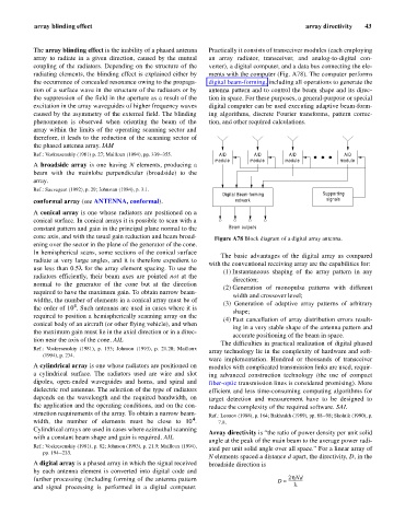
The array blinding effect is the inability of a phased antenna Practically it consists of transceiver modules (each employing
array to radiate in a given direction, caused by the mutual an array radiator, transceiver, and analog-to-digital con-
coupling of the radiators. Depending on the structure of the verter), a digital computer, and a data bus connecting the ele-
radiating elements, the blinding effect is explained either by ments with the computer (Fig. A78). The computer performs
the occurrence of concealed resonance owing to the propaga- digital beam-forming, including all operations to generate the
tion of a surface wave in the structure of the radiators or by antenna pattern and to control the beam shape and its direc-
the suppression of the field in the aperture as a result of the tion in space. For these purposes, a general-purpose or special
excitation in the array waveguides of higher frequency waves digital computer can be used executing adaptive beam-form-
caused by the asymmetry of the external field. The blinding ing algorithms, discrete Fourier transforms, pattern correc-
phenomenon is observed when orienting the beam of the tion, and other required calculations.
array within the limits of the operating scanning sector and
therefore, it leads to the reduction of the scanning sector of
the phased antenna array. IAM
Ref.: Voskresenskiy (1981) p. 27; Mailloux (1994), pp. 339–355. A/D A/D A/D A/D
module module module module
A broadside array is one having N elements, producing a
beam with the mainlobe perpendicular (broadside) to the
array.
Ref.: Sauvageot (1992), p. 29; Johnston (1984), p. 3.1.
Digital Beam-forming Supporting
conformal array (see ANTENNA, conformal). network signals
A conical array is one whose radiators are positioned on a
conical surface. In conical arrays it is possible to scan with a
constant pattern and gain in the principal plane normal to the Beam outputs
cone axis, and with the usual gain reduction and beam broad- Figure A78 Block diagram of a digital array antenna.
ening over the sector in the plane of the generator of the cone.
In hemispherical scans, some sections of the conical surface
The basic advantages of the digital array as compared
radiate at very large angles, and it is therefore expedient to
with the conventional receiving array are the capabilities for:
use less than 0.5l for the array element spacing. To use the
(1) Instantaneous shaping of the array pattern in any
radiators efficiently, their beam axes are pointed not at the
direction;
normal to the generator of the cone but at the direction
(2) Generation of monopulse patterns with different
required to have the maximum gain. To obtain narrow beam-
width and crossover level;
widths, the number of elements in a conical array must be of (3) Generation of adaptive array patterns of arbitrary
4
the order of 10 . Such antennas are used in cases where it is
shape;
required to position a hemispherically scanning array on the
(4) Fast cancellation of array distribution errors result-
conical body of an aircraft (or other flying vehicle), and when
ing in a very stable shape of the antenna pattern and
the maximum gain must lie in the axial direction or in a direc-
accurate positioning of the beam in space.
tion near the axis of the cone. AIL
The difficulties in practical realization of digital phased
Ref.: Voskresenskiy (1981), p. 153; Johnson (1993), p. 21.20; Mailloux
array technology lie in the complexity of hardware and soft-
(1994), p. 234.
ware implementation. Hundred or thousands of transceiver
A cylindrical array is one whose radiators are positioned on modules with complicated transmission links are used, requir-
a cylindrical surface. The radiators used are wire and slot ing advanced construction technology (the use of compact
dipoles, open-ended waveguides and horns, and spiral and fiber-optic transmission lines is considered promising). More
dielectric rod antennas. The selection of the type of radiators efficient and less time-consuming computing algorithms for
depends on the wavelength and the required bandwidth, on target detection and measurement have to be designed to
the application and the operating conditions, and on the con- reduce the complexity of the required software. SAL
struction requirements of the array. To obtain a narrow beam- Ref.: Leonov (1988), p. 164; Bakhrakh (1989), pp. 88–98; Skolnik (1990), p.
4
width, the number of elements must be close to 10 . 7.8.
Cylindrical arrays are used in cases where azimuthal scanning
Array directivity is “the ratio of power density per unit solid
with a constant beam shape and gain is required. AIL
angle at the peak of the main beam to the average power radi-
Ref.: Voskresenskiy (1981), p. 82; Johnson (1993), p. 21.9; Mailloux (1994), ated per unit solid angle over all space.” For a linear array of
pp. 194–233.
N elements spaced a distance d apart, the directivity, D, in the
A digital array is a phased array in which the signal received broadside direction is
by each antenna element is converted into digital code and
further processing (including forming of the antenna pattern D » 2hNd
--------------
and signal processing is performed in a digital computer. l