
Page 56 - Radar Technology Encyclopedia
P. 56
46 array (aperture) matching array, monopulse
(3) Using a thin dielectric sheet having a high depends on the number of elements N and N in each linear
2
1
dielectric permeability, positioned a small distance from the array, and the spacing between the elements d and d . The
2
1
waveguide array. array antenna is named after its inventor. AIL
(4) Using a close spacing of the radiating elements. Ref.: Steinberg (1963), pp. 78–82; Fradin (1977), p. 348.
The most wideband methods are those that reduce element
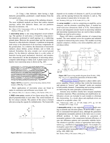
An array module is a device comprising an amplifier, active
spacings, utilize thin dielectric sheets, and use partitions
elements, and the elements controlling them. A module has
between the elements. AIL
small transverse dimensions (0.6l to 0.7l). Semiconductor
Ref.: Oliner (1972); Voskresenskiy (1981), p. 38; Skolnik (1990), p. 7.22; devices and integrated circuits based on microstrip radiators
Mailloux (1994), pp. 367–387.
and microstrip transmission lines are used in these modules.
A microstrip array is one using integrated circuit technol- Modules are used in active arrays.
ogy. The aperture of such arrays is formed by using micros- Figure A85 shows a possible structure of a transceiving
trip elements, positioned at small spacings on a conducting module. The same radiator serves for reception and radiation
ground plane. Between the ground plane and the microstrip of signals in transceiving active arrays. The module receiving
elements is a thin dielectric substrate. A problem in designing channel comprises a limiter, a low-noise amplifier, and a con-
such arrays is the placement of all necessary components on trol phase shifter.
the ground plane. As a solution, the dimensions of microstrip
radiators, phase shifters, power dividers, and so forth, are
reduced. Sometimes the array extends over several ground
planes. For the dielectric substrate there is a wide variety of
materials having good mechanical, electrical, and tempera-
ture characteristics. In the development of microstrip arrays,
computer-aided design is widely used. A photo mask of a mil-
limeter-wave microstrip array is shown in Fig. A83.
Figure A85 Transceiving module diagram (from Skolnik, 1990,
Fig. 5.9, p. 5.17, reprinted by permission of McGraw-Hill).
The transmitting channel comprises a phase shifter and a
Figure A83 Photo mask for a microstrip array antenna (from power amplifier. Power switches that switch the heterodyne
Leonov, 1988, Fig. 5.4, p. 168). and antenna in “receive” and “transmit” modes are common
to both module channels. Transmitting and receiving modules
Basic applications of microstrip arrays are found in
are built using the same principles examined above.
radars in centimeter and millimeter wave bands. AIL
Antenna array modules usually have unequal amplitude
Ref.: Johnson (1993), Ch. 7; Sazonov (1988), p. 258; Zurcher (1995), Ch. 2.
and phase responses. Phase autotuning and amplification sta-
A Mill’s cross array consists of two linear arrays (Fig. A84), bilization circuits are included in each module to eliminate
placed perpendicularly to each other. The central elements of this shortcoming. As a result, phase and amplitude errors are
the two arrays coincide. The pattern of this array is formed reduced to acceptable values. AIL
after processing the signals by multiplication. The beamwidth
Ref.: Voskresenskiy (1981), pp. 247–258; Fradin (1977), pp. 343–345;
Brookner (1977), Chaps. 19, 20.
N
2
A monopulse array is one supporting monopulse angle sens-
d 2 ing in azimuth and elevation planes. It can be either a space-
fed or constrained-feed phased array, although the generation
d 1 of appropriate monopulse patterns in the latter case is a more
1 2 N difficult problem. A basic problem in generation of
1
monopulse patterns is the compromise between efficiency of
sum and difference patterns and reasonable sidelobe levels.
The solution is typically a choice of appropriate feed configu-
ration (e.g., multihorn or dual-ladder feeds). An example of a
monopulse space-fed is the Grill Pan shown in Fig. F18, and
2 a constrained-feed monopulse array is the AN/SPY-1 shown
1 in Fig. A86. DKB, SAL
Figure A84 Mill’s cross antenna array.
Ref.: Barton (1988), p.198; Leonov (1986), p. 23.