
Page 60 - Radar Technology Encyclopedia
P. 60
50 array, surface array, wideband
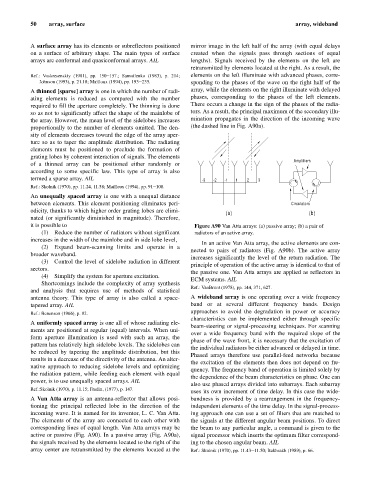
A surface array has its elements or subreflectors positioned mirror image in the left half of the array (with equal delays
on a surface of arbitrary shape. The main types of surface created when the signals pass through sections of equal
arrays are conformal and quasiconformal arrays. AIL lengths). Signals received by the elements on the left are
retransmitted by elements located at the right. As a result, the
Ref.: Voskresenskiy (1981), pp. 150–157.; Samoilenko (1983), p. 214; elements on the left illuminate with advanced phases, corre-
Johnson (1993), p. 21.18; Mailloux (1994), pp. 193–235. sponding to the phases of the wave on the right half of the
A thinned [sparse] array is one in which the number of radi- array, while the elements on the right illuminate with delayed
ating elements is reduced as compared with the number phases, corresponding to the phases of the left elements.
required to fill the aperture completely. The thinning is done There occurs a change in the sign of the phases of the radia-
so as not to significantly affect the shape of the mainlobe of tors. As a result, the principal maximum of the secondary illu-
the array. However, the mean level of the sidelobes increases mination propagates in the direction of the incoming wave
proportionally to the number of elements omitted. The den- (the dashed line in Fig. A90a).
sity of elements decreases toward the edge of the array aper-
ture so as to taper the amplitude distribution. The radiating
elements must be positioned to preclude the formation of
grating lobes by coherent interaction of signals. The elements
Amplifiers
of a thinned array can be positioned either randomly or
according to some specific law. This type of array is also
termed a sparse array. AIL -3 -2 -1 1 2 3
Ref.: Skolnik (1970), pp. 11.24, 11.58; Mailloux (1994), pp. 91–108.
An unequally spaced array is one with a unequal distance
between elements. This element positioning eliminates peri- Circulators
odicity, thanks to which higher order grating lobes are elimi-
(a) (b)
nated (or significantly diminished in magnitude). Therefore,
it is possible to Figure A90 Van Atta arrays: (a) passive array; (b) a pair of
(1) Reduce the number of radiators without significant radiators of an active array.
increases in the width of the mainlobe and in side lobe level,
In an active Van Atta array, the active elements are con-
(2) Expand beam-scanning limits and operate in a
nected to pairs of radiators (Fig. A90b). The active array
broader waveband.
increases significantly the level of the return radiation. The
(3) Control the level of sidelobe radiation in different
principle of operation of the active array is identical to that of
sectors.
the passive one. Van Atta arrays are applied as reflectors in
(4) Simplify the system for aperture excitation.
ECM systems. AIL
Shortcomings include the complexity of array synthesis
Ref.: VanBrunt (1978), pp. 144, 371, 627.
and analysis that requires use of methods of statistical
antenna theory. This type of array is also called a space- A wideband array is one operating over a wide frequency
tapered array. AIL band or at several different frequency bands. Design
approaches to avoid the degradation in power or accuracy
Ref.: Benenson (1966), p. 82.
characteristics can be implemented either through specific
A uniformly spaced array is one all of whose radiating ele-
beam-steering or signal-processing techniques. For scanning
ments are positioned at regular (equal) intervals. When uni-
over a wide frequency band with the required slope of the
form aperture illumination is used with such an array, the
phase of the wave front, it is necessary that the excitation of
pattern has relatively high sidelobe levels. The sidelobes can
the individual radiators be either advanced or delayed in time.
be reduced by tapering the amplitude distribution, but this
Phased arrays therefore use parallel-feed networks because
results in a decrease of the directivity of the antenna. An alter-
the excitation of the elements then does not depend on fre-
native approach to reducing sidelobe levels and optimizing
quency. The frequency band of operation is limited solely by
the radiation pattern, while feeding each element with equal
the dependence of the beam characteristics on phase. One can
power, is to use unequally spaced arrays. AIL
also use phased arrays divided into subarrays. Each subarray
Ref.:Skolnik (1970), p. 11.15; Fradin, (1977), p. 147.
uses its own increment of time delay. In this case the wide-
A Van Atta array is an antenna-reflector that allows posi- bandness is provided by a rearrangement in the frequency-
tioning the principal reflected lobe in the direction of the independent elements of the time delay. In the signal-process-
incoming wave. It is named for its inventor, L. C. Van Atta. ing approach one can use a set of filters that are matched to
The elements of the array are connected to each other with the signals at the different angular beam positions. To direct
corresponding lines of equal length. Van Atta arrays may be the beam to any particular angle, a command is given to the
active or passive (Fig. A90). In a passive array (Fig. A90a), signal processor which inserts the optimum filter correspond-
the signals received by the elements located to the right of the ing to the chosen angular beam. AIL
array center are retransmitted by the elements located at the Ref.: Skolnik (1970), pp. 11.43–11.50; Bakhrakh (1989), p. 66.