Page 64 - Radar Technology Encyclopedia
P. 64

54    atmospheric refraction                                                 atmospheric refractive index


           somewhat larger angle than the direct geometric path to the
           target (Fig. A94).                                                                    1  2
                                                                                                            h
                                                                                                             0
                                                                                                      3  5
                                                                                                  a
                                                                                                  4  4          4'
                                                   Target        A                  Y                          5'
                                                                    h           h               h
                                                                     A           Y               A
                  Radar                                                   (a)                         (b)
                                 q
                                      Dq
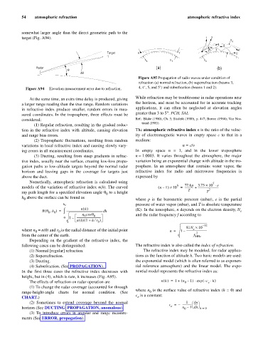
                                                                 Figure A95 Propagation of radio waves under condition of
                                                                 refraction (a) normal refraction, (b) superrefraction (beams 3,
             Figure A94   Elevation measurement error due to refraction.  4, 4’, 5, and 5’) and subrefraction (beams 1 and 2).

                                                                While refraction may be troublesome in radar operations near
               At the same time, an extra time delay is produced, giving
                                                                the horizon, and must be accounted for in accurate tracking
           a larger range reading than the true range. Random variations
                                                                applications, it can often be  neglected at  elevation angles
           in refractive index produce smaller, random errors in mea-
                                                                greater than 3 to 5°. PCH, SAL
           sured coordinates. In the troposphere, three effects must be
           considered:                                          Ref.: Blake (1980), Ch. 5; Skolnik (1980), p. 447; Barton (1988); Van Nos-
                                                                   trand (1983).
                 (1) Regular refraction, resulting in the gradual reduc-
           tion in the  refractive index with  altitude, causing  elevation  The atmospheric refractive index n is the ratio of the veloc-
           and range bias errors.                               ity of electromagnetic waves in empty space  c to that in a
                 (2) Tropospheric fluctuations, resulting from random  medium:
           variations in local refractive index and causing slowly vary-              n = c/v
           ing errors in all measurement coordinates.           In empty  space  n = 1, and  in  the lower  troposphere
                 (3) Ducting, resulting from steep gradients in refrac-  n »1.0003. It varies throughout the  atmosphere, the  major
           tive index, usually near the surface, creating low-loss propa-  variation being an exponential change with altitude in the tro-
           gation paths to low-altitude targets beyond the normal radar  posphere. In an atmosphere that contains water vapor, the
           horizon and leaving gaps in the coverage for targets just  refractive index for  radio and  microwave frequencies is
           above the duct.                                      expressed by
               Numerically, atmospheric refraction is calculated using                              5
                                                                                   6   77.6p  3.73 ´ 10 × e
                                                                                ´
           models of the variation of refractive index n(h). The curved   ( n –  1 ) 10 =  ------------- +  --------------------------------
                                                                                        T         2
           ray path length for a specified elevation angle q  to a height                        T
                                                  0
           h  above the surface can be found as
            0                                                   where  p is the barometric pressure (mbar),  e is the partial
                                                                pressure of water vapor (mbar), and T is absolute temperature
                              h 0
                                       nh ()                    (K). In the ionosphere, n depends on the electron density, N
                      (
                     R q h ) =  ò -------------------------------------------------------- hd                    e
                        ,
                        0  0
                                       n cos q 0                and the radar frequency f according to
                                        0
                               0  1 –  -------------------------------------
                                        (
                                     nh () 1 +  hr ¤ )
                                              0
                                                                                               – 12
                                                                                        81N ´ 10
                                                                                           e
           where n  = n(0) and r  is the radial distance of the initial point   n =  1 –  --------------------------------
                 0
                            0
                                                                                            2
           from the center of the earth.                                                   f MHz
               Depending on  the  gradient of  the refractive  index, the
           following cases can be distinguished:                The refractive index is also called the index of refraction.
               (1) Normal [regular] refraction.                     The refractive index may be modeled, for radar applica-
               (2) Superrefraction.                             tions as the function of altitude h. Two basic models are used:
               (3) Ducting.                                     the exponential model (which is often referred to as exponen-
               (4) Subrefraction. (See PROPAGATION).            tial reference  atmosphere) and the  linear model.  The  expo-
           In the  first  three cases  the refractive index  decreases  with  nential model represents the refractive index as:
           height, but in (4), which is rare, it increases (Fig. A95).
                                                                                           ×
               The effects of refraction on radar operation are             nh )(  =  1 +  ( n –  1 )exp  c – (  e  h × )
                                                                                       0
               (1) To change the radar coverage (accounted for through
                                                                where n  is the surface value of refractive index (h = 0) and
           range-height-angle charts for normal condition. (See        0
                                                                c  is a constant:
           CHART.)                                               e
               (2) Sometimes to extend coverage beyond the normal                      1  æ dn ö
                                                                                c =  –  -------------- ------
                                                                                e
                                                                                         1 dh ø
           horizon (See DUCTING; PROPAGATION, anomalous).                             n – è   h =  0
                                                                                       0
               (3) To introduce errors in angular and range measure-
           ments (See ERROR, propagation).
   59   60   61   62   63   64   65   66   67   68   69