
Page 65 - Radar Technology Encyclopedia
P. 65
atmospheric refractive index attenuation by clear air 55
Values of n and c vary at different times and places. The lin- The consequences of (3) are generally negligible for
0
e
ear model assumes a constant negative gradient k of the index radars operating below the millimeter-wave frequencies
of refraction: (35 GHz to 140 GHz). (See ATTENUATION; PROPAGA-
TION; RADAR, doppler; RADAR, millimeter wave).
nh () n – ×
=
k h
0 PCH
Ref.: Van Nostrand (1983); Currie (1987), pp. 9, 46.
that results in the four-thirds approximation widely used in
radar range calculations. The ray bending for the exponential An atmospheric window is a narrow portion of the electro-
model is slightly greater at h = 0, but rapidly becomes less magnetic spectrum for which the propagation losses due to
than for linear model as altitude increases. The linear model is signal attenuation are relatively low compared with that of
realistic at altitudes up to about 10,000 ft. (3 km), but predicts adjacent regions. For example, at millimeter-wave frequen-
excessive ray bending at higher altitudes. The main purpose cies, radar operation is usually restricted to “windows” at 35,
of atmospheric models is to provide an instrument to evaluate 95, 140, 220, and 440 GHz. (See also ATTENUATION).
radar performance under the conditions of refraction in atmo- PCH
sphere. Ref.: Currie (1987), p. 8; Brussard (1995).
A scaled-up parameter called refractivity is defined as
ATMOSPHERICS are “transient bursts of electromagnetic
radiation arising from natural electrical disturbances in the
×
N = ( n – 1 )10 6
s 0 lower atmosphere.” The most powerful atmospherics arise
from thunderstorm electric discharges. When the wavelength
The values N = 313 and c = 0.1439/km are average for the
e
s
U.S. at sea level and typically regarded as a standard atmo- is less than 20m, atmospherics practically have no effect upon
electronics hardware. SAL
sphere model. SAL, PCH
Ref.: IEEE (1993), p. 61; Popov (1980), p. 43; Jordan (1985), p. 34.2.
Ref.: Van Vleck, J. H., The Absorption of Microwaves by Oxygen, Physical
Review 71, April 1947, pp. 413–424; Currie (1987); Blake (1982), ATTENUATION is the reduction in power resulting from
p. 182; (1980), p. 178; Skolnik (1980), p. 448.
absorption along an atmospheric path or in a circuit. The cir-
Atmospheric turbulence. The motion of air in the atmo- cuit element intended to reduce power is an ATTENUATOR.
sphere is usually accompanied by turbulence: the presence of The following sections discuss unintentional attenuation in
eddies of various sizes that migrate to become part of the paths through the atmosphere and other environments.
main airstream or of other eddies or that dissipate shortly
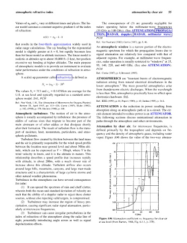
Attenuation by clear air, for microwave frequencies, is
after their formation. The result of turbulent flow is the trans-
defined primarily by the troposphere and depends on fre-
port of moisture, heat, momentum, particulates, and atmo-
quency and the density of atmospheric gases, including water
spheric pollutants.
vapor. Figure A96 shows the value of the two-way attenua-
Turbulent flow created by friction between the land mass
and the air is primarily responsible for the wind-speed profile
between the location near ground level and about 500m alti-
tude, which can be expressed as V = 10logh, where V is the
wind velocity in knots, and h is the altitude in meters. This
relationship describes a speed profile that increases rapidly
with altitude, to about 200m, with a much slower rate of
increase above this altitude. Turbulent airflow also occurs
around large hills, mountains, canyons, and large man-made
structures and is a characteristic of large cyclonic storms and
other natural weather phenomena.
Turbulence in the atmosphere can have several consequences
for radar:
(1) It can spread the spectrum of rain and chaff clutter,
wherein both the mean and standard deviation of velocity are
such that the ability of a doppler radar to reject these clutter
sources, without also rejecting valid targets, is compromised.
(2) Turbulence may increase the region of heavy pre-
cipitation, causing significant radar signal attenuation, partic-
ularly at microwave frequencies.
(3) Turbulence can cause irregular perturbations in the
index of refraction of the atmosphere along the radar line of
Figure A96 Attenuation coefficient vs. frequency for clear air
sight, potentially introducing angle errors as well as signal
at sea level (from Barton, 1988, Fig. 6.1.1, p. 279).
depolarization effects.