
Page 70 - Radar Technology Encyclopedia
P. 70
60 AXIS backward-wave tube, M-type
AXIS The backscattering cross section is “the scattering cross sec-
tion in the direction towards the source.” (see RADAR
The antenna axis can be the electrical reference axis of the
CROSS SECTION).
antenna or the mechanical (boresight) axis. The first is the
Ref.: IEEE (1993), p. 85
axis going from the antenna phase center through the peak of
the mainlobe, while the latter is the axis of symmetry. When Bragg backscattering resonance conditions are the condi-
electrical reference axis and boresight axis do not coincide, tions defining when the resultant radar backscatter can be
the angular difference is termed boresight error and must be interpreted as that obtained from the component of the sea
accounted for in the measurement of target directions. SAL spectrum that is “resonant” with the radar wavelength
Ref.: Skolnik (1990), p. 6.5.
l = 2l cos y
r
w
The null axis is the term denoting equisignal direction in
amplitude-comparison monopulse systems (Fig. A104). SAL where l is the radar wavelength, l is the water wavelength,
w
r
and y is grazing angle.
Ref.: Leonov (1986), p. 2.
The Bragg scattering resonance condition is termed so
Beam 1
because of its similarity to the x-ray scattering in crystals
Null axis
observed by Bragg. In radar applications it is used in the the-
Beam 2
ory of sea clutter. SAL
Ref.: Skolnik (1980), p. 480.
Voltage
BACKWARD-WAVE TUBE. A backward-wave tube is a
microwave electronic device using a long interaction between
S a bunched electron current, moving in longitudinal or perpen-
dicular electrical and magnetic fields, and a backward har-
monic wave propagating along a slow-wave circuit.
Depending on the directions of the electrical and magnetic
waves, a tube may be described as an M-type or O-type back-
D
ward-wave tube. The physical processes underlying the inter-
Null axis
action between the electrons and the wave in a backward-
Figure A104 Null axis of amplitude comparison monopulse
wave tube are the same as those in a travelling-wave tube. The
system.
difference is that in a backward-wave tube, the electron cur-
AZIMUTH (see ANGLE, azimuth). rent interacts with a backward spatial harmonic. The electron
velocity vector v and the backward wave group velocity vec-
p
tor v are opposed in direction to the group velocity vector v g
f
for the main wave, for O-type backward-wave tube.
B Particular features of the tube depend on whether it is M-
or O-type. IAM
BACKSCATTER, BACKSCATTERING. Backscatter is Ref.: IEEE (1993), p. 86; Dulin (1972), pp. 58, 71; Fink (1982), p. 9.54.
“the energy reflected in a direction opposite to that of incident
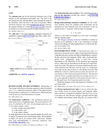
An M-type backward-wave tube is one in which the elec-
wave,” (i.e., redirected toward the radar). If the signal formed
tron current moves in crossed electric and magnetic fields,
by backscatter is undesired, it is called clutter. Backscattering
and is similar to a magnetron amplifier. The slow-wave circuit
is the process by which backscatter is formed.
is an open coil. The electron current is formed with the help
Ref.: IEEE (1993), p. 85.
of a cathode and auxiliary anode (Fig. B1). In contrast with a
The backscatter coefficient is the normalized measure of
radar return from a distributed target. The usual notation is s 0 E
0
or h . It is defined as s = s/A for area targets and as h = s/ Electron current Anode
v
v
c
V for volume targets, where
c
s is the average monostatic RCS.
A is the surface area.
c
V is the clutter volume. Output port B
c
In radar applications this term typically applies to clutter and +
to targets of scatterometers and imaging radars. When applied Cold cathode
0
to clutter, s and h are termed clutter reflectivity. Another Auxilliary
v
term used interchangeably is scattering coefficient. (See anode Collector
CLUTTER reflectivity.) SAL Cathode Absorber
Ref.: IEEE (1990), p. 6; (1993), p. 85; Nathanson (1990), pp. 17, 199.
Figure B1 M-type backward-wave tube.