
Page 71 - Radar Technology Encyclopedia
P. 71
backward-wave tube, M-type bandwidth, narrow bandwidth assumption 61
magnetron amplifier, the power is tapped from an output line frequency and separated by the modulation frequency and its
located near the cathode. In an amplifying backward-wave harmonics. For example, if the carrier frequency w is modu-
0
tube, the input line is located near the collector, without an lated by a sinusoidal waveform with frequency W, where
absorber. The slow-wave circuit consists of built-in pins. The W << w , the output spectrum will have sidebands at w ± W.
0
0
tube is generally cylindrical. AIL
M-type backward-wave tubes may be amplifiers or oscil- Ref.: Popov (1980), p. 54; Schwartz (1959), pp. 93, 121.
lators, operating at medium to high power levels from 1 to 90
BANDWIDTH. The term bandwidth is defined generally to
GHz (see OSCILLATOR, backward-wave tube; and
refer to the frequency interval occupied by a signal or passed
AMPLIFIER, backward-wave tube). IAM
by a filter or other device. The conventional symbol is B. Sev-
Ref.: Andrushko (1981), p. 77; Gilmour (1986), p. 407.
eral different bandwidths have been defined and used in the
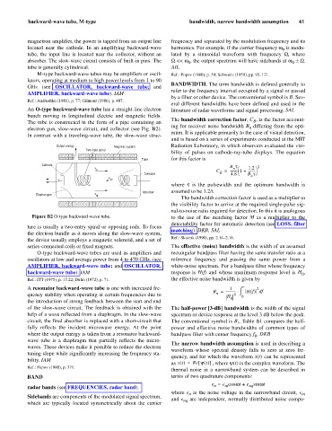
An O-type backward-wave tube has a straight-line electron literature of radar waveforms and signal processing. SAL
bunch moving in longitudinal electric and magnetic fields.
The bandwidth correction factor, C , is the factor account-
B
The tube is constructed in the form of a pipe containing an
ing for receiver noise bandwidth B differing from the opti-
n
electron gun, slow-wave circuit, and collector (see Fig. B2).
mum. It is applicable primarily to the case of visual detection,
In contrast with a traveling-wave tube, the slow-wave struc-
and is based on a series of experiments conducted at the MIT
Output energy Magnetic system Radiation Laboratory, in which observers evaluated the visi-
Two-input spiral
bility of pulses on cathode-ray-tube displays. The equation
Tube for this factor is
Cathode B t 2
v n æ 1.2 ö
p C = --------- 1 + ---------
Collector B 4.8 è B tø
n
v gp
i
where t s the pulsewidth and the optimum bandwidth is
Absorber assumed to be 1.2/t.
Electron gun v f
The bandwidth correction factor is used as a multiplier to
the visibility factor to arrive at the required single-pulse sig-
nal-to-noise ratio required for detection. In this it is analogous
Figure B2 O-type backward-wave tube. to the use of the matching factor M as a multiplier to the
detectability factor for automatic detection (see LOSS, filter
ture is usually a two-entry spiral or opposing rods. To focus
matching). DKB, SAL
the electron bundle as it moves along the slow-wave system,
Ref.: Skolnik (1990), pp. 2.14–2.16.
the device usually employs a magnetic solenoid, and a set of
series-connected coils or fixed magnets. The effective (noise) bandwidth is the width of an assumed
O-type backward-wave tubes are used as amplifiers and rectangular bandpass filter having the same transfer ratio at a
oscillators at low and average power from 4 to 470 GHz. (see reference frequency and passing the same power from a
AMPLIFIER, backward-wave tube; and OSCILLATOR, white-noise spectrum. For a bandpass filter whose frequency
backward-wave tube). IAM response is H(f) and whose maximum response level is H ,
0
Ref.: ITT (1975), p. 17.22; Dulin (1972), p. 71. the effective noise bandwidth is given by
A resonator backward-wave tube is one with increased fre- 1 ¥ 2
2 ò
B = ------------ × Hf () f
d
n
quency stability when operating at certain frequencies due to H 0 0
the introduction of strong feedback between the start and end
of the slow-wave circuit. The feedback is obtained with the The half-power [3-dB] bandwidth is the width of the signal
help of a wave reflected from a diaphragm. In the slow-wave spectrum or device response at the level 3 dB below the peak.
circuit, the final absorber is replaced with a short-circuit that The conventional symbol is B . Table B1 compares the half-
3
fully reflects the incident microwave energy. At the point power and effective noise bandwidths of common types of
where the output energy is taken from a resonator backward- bandpass filter with center frequency f . DKB
0
wave tube is a diaphragm that partially reflects the micro-
The narrow bandwidth assumption is used in describing a
waves. These devices make it possible to reduce the electron
waveform whose spectral density falls to zero at zero fre-
tuning slope while significantly increasing the frequency sta-
quency, and for which the waveform s(t) can be represented
bility. IAM
as st () Re y t ()[ ]
=
, where y(t) is the complex waveform. The
Ref.: Popov (1980), p. 371.
thermal noise in a narrowband system can be described in
BAND terms of two quadrature components:
e = e coswt + e sinwt
nq
n
ni
radar bands (see FREQUENCIES, radar band).
where e is the noise voltage in the narrowband circuit, e ni
n
Sidebands are components of the modulated signal spectrum,
and e are independent, normally distributed noise compo-
nq
which are typically located symmetrically about the carrier