
Page 74 - Radar Technology Encyclopedia
P. 74
64 beam steering BLINKING
Beam steering is changing the direction of the mainlobe of interrupted continuous-wave radars to eliminate transients,
the antenna pattern, often in accordance with a prescribed spillover, and close-in clutter. SAL
scanning pattern. The radar subsystem that controls beam Ref.: Barton (1988), p. 270; Nathanson (1990), p. 368.
steering is termed a beam-steering unit. In mechanically
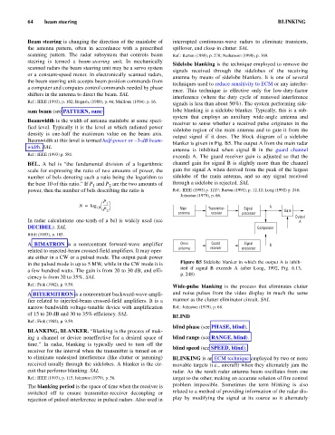
Sidelobe blanking is the technique employed to remove the
scanned radars the beam steering unit may be a servo system
signals received through the sidelobes of the receiving
or a constant-speed motor. In electronically scanned radars,
antenna by means of sidelobe blankers. It is one of several
the beam steering unit accepts beam position commands from
techniques used to reduce sensitivity to ECM or any interfer-
a computer and computes control commands needed by phase
ence. This technique is effective only for low-duty-factor
shifters in the antenna to direct the beam. SAL
interference (where the duty cycle of removed interference
Ref.: IEEE (1993), p. 102; Bogush, (1989), p. 46; Mailloux (1994). p. 16.
signals is less than about 50%). The system performing side-
sum beam (see PATTERN, sum). lobe blanking is a sidelobe blanker. Typically, this is a sub-
system that employs an auxiliary wide-angle antenna and
Beamwidth is the width of antenna mainlobe at some speci-
receiver to sense whether a received pulse originates in the
fied level. Typically it is the level at which radiated power
sidelobe region of the main antenna and to gate it from the
density is one-half the maximum value on the beam axis.
output signal if it does. The block diagram of a sidelobe
Beamwidth at this level is termed half-power or -3-dB beam-
blanker is given in Fig. B5. The output A from the main radar
width. SAL
antenna is inhibited when signal B in the guard channel
Ref.: IEEE (1993) p. 581.
exceeds A. The guard receiver gain is adjusted so that the
BEL. A bel is “the fundamental division of a logarithmic channel gain for signal B is slightly more than the channel
scale for expressing the ratio of two amounts of power, the gain for signal A when derived from the peak of the largest
number of bels denoting such a ratio being the logarithm to sidelobe of the main antenna, and so any signal received
the base 10 of this ratio.” If P and P are the two amounts of through a sidelobe is rejected. SAL
2
1
power, then the number of bels describing the ratio is Ref.: IEEE (1993) p. 1217; Barton (1991), p. 12.12; Long (1992) p. 248;
Johnston (1979), p. 66.
P 1 ö
N = log æ ------
10 è P ø Main Transmitter- Signal A
2 Gate
antenna receiver processor
Output
In radar calculations one-tenth of a bel is widely used (see A
DECIBEL). SAL Comparator
IEEE (1993), p. 103.
A BIMATRON is a nonreentrant forward-wave amplifier Omni Guard Signal B
antenna receiver processor
related to injected-beam crossed-field amplifiers. It may oper-
ate either in a CW or a pulsed mode. The output peak power
in the pulsed mode is up to 5 MW, while in the CW mode it is Figure B5 Sidelobe blanker in which the output A is inhib-
ited if signal B exceeds A (after Long, 1992, Fig. 6.13,
a few hundred watts. The gain is from 20 to 30 dB, and effi-
p. 248).
ciency is from 20 to 35%. SAL
Ref.: Fink (1982), p. 9.59. Wide-pulse blanking is the process that eliminates clutter
A BITERMITRON is a nonreentrant backward-wave ampli- and noise pulses from the video display in much the same
fier related to injected-beam crossed-field amplifiers. It is a manner as the clutter eliminator circuit. SAL
narrow-bandwidth voltage-tunable device with amplification Ref.: Johnston (1979), p. 68.
of 15 to 20 dB and 30 to 35% efficiency. SAL
BLIND
Ref.: Fink (1982), p. 9.59.
blind phase (see PHASE, blind).
BLANKING, BLANKER. “Blanking is the process of mak-
ing a channel or device noneffective for a desired space of blind range (see RANGE, blind).
time.” In radar, blanking is typically used to turn off the
blind speed (see SPEED, blind).
receiver for the interval when the transmitter is turned on or
to eliminate undesired interference (like clutter or jamming) BLINKING is an ECM technique employed by two or more
received usually through the sidelobes. A blanker is the cir- movable targets (i.e., aircraft) when they alternately jam the
cuit that performs blanking. SAL radar. As the result radar antenna beam oscillates from one
Ref.: IEEE (1993), p. 115; Johnston (1979), p. 56. target to the other, making an accurate solution of fire control
The blanking period is the space of time when the receiver is problem impossible. Sometimes the term blinking is also
switched off to ensure transmitter-receiver decoupling or related to a method of providing information of the radar dis-
rejection of pulsed interference in pulsed radars. Also used in play by modifying the signal at its source so it alternately