Page 79 - Radar Technology Encyclopedia
P. 79

canceler, double-delay                                                 canceler, multiple-delay(-line)  69


                                f r  4    v b  4                        Radar           Auxiliary antennas
                                        æ
                              æ
                                                                       antenna
                         I =  2 ------------  ö  =  2 ------------  ö           1       2              3
                          2   è 2ps ø   è 2ps ø
                                  c         v
                                                                          M      A       A              A
           where f  is pulse repetition frequency, s  is rms clutter spread       1       2              3
                 r
                                           c
           in frequency, v  is the blind speed, and s  is the rms clutter  Adaptive   Adaptive       Adaptive
                                             v
                                                                         loop
                       b
                                                                                                        loop
                                                                                         loop
           spread in velocity. SAL
                                                                          R                             R  4
           Ref.: Barton (1964), p. 219; Skolnik (1980), p. 109.            1
                                                                      Adaptive           R  2        Adaptive
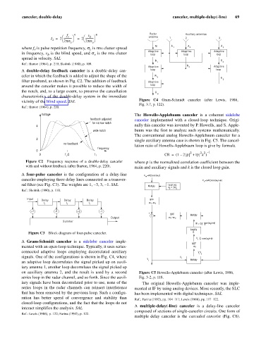
           A  double-delay feedback canceler is a double-delay can-      loop                           loop
           celer in which the feedback is added to adjust the shape of the  R
                                                                           3
                                                                                                        R
           filter passband, as shown in Fig. C2. The addition of feedback  Adaptive                      5
           around the canceler makes it possible to reduce the width of     loop
           the notch, and, to a large extent, to preserve the cancellation  R
                                                                           6
           characteristics of the double-delay system in the immediate
           vicinity of the blind speed. SAL                       Figure C4 Gram-Schmidt canceler (after Lewis, 1986,
                                                                  Fig. 3.7, p. 122).
           Ref.: Barton (1964), p. 220.
                     Voltage                                    The  Howells-Applebaum canceler  is a coherent  sidelobe
                                           feedback adjusted    canceler implemented with  a  closed-loop technique. Origi-
                                            for narrow notch
                  4                                             nally this canceler was invented by P. Howells, and S. Apple-
                                             wide notch         baum was the first to analyze such systems mathematically.
                                                                The conventional analog Howells-Applebaum canceler for a
                  2
                                                                single auxiliary antenna case is shown in Fig. C5. The cancel-
                               no feedback
                                                                lation ratio of Howells-Applebaum loop is give by formula
                                               frequency
                  0
                                                                                          2    2 2 –  1
                   0            f  /2        f r                              CR =  ( 1 –  2 r +  |r k )
                                r
             Figure C2  Frequency response  of  a double-delay canceler  where r is the normalized correlation coefficient between the
             with and without feedback (after Barton, 1964, p. 220).  main and auxiliary signals and k is the closed loop gain.
           A  four-pulse canceler  is the configuration of a delay-line  V m =A(t)cos(w 1 t)
           canceler employing three delay lines connected as a transver-                        V a =aA(t)cos(w 1 t+f )
           sal filter (see Fig. C3). The weights are 1, -3, 3, -1. SAL  Multiply  Local osc.
                                                                                   f
                                                                                w  = 2p
                                                                                    2
                                                                                2
           Ref.: Skolnik (1980), p. 110.
              Input                                                    BPF
                    Delay      Delay      Delay
                                                                       w  -w
                      t r       t r        t r                          1  2
                +1         -3        +3         -1
                                                                       +  -      BPF
                                                                        S                 Multiply
                                                     Output                      1 w  -w
                                                                                   2
                               Summer
                                                                                                r
                                                                                             W = GV  V a cos(w 2 t+f )
                                                                                          Amplify
              Figure C3  Block diagram of four-pulse canceler.                             G
                                                                                             V   V cos(w 2 t+f )
                                                                                             r
                                                                                               a
           A  Gram-Schmidt canceler  is a  sidelobe canceler imple-
                                                                                           NBF
           mented with an open-loop technique. Typically, it uses series-                   w 2
           connected adaptive loops employing decorrelated auxiliary                          V V
                                                                                              ra
           signals. One of the configurations is shown in Fig. C4, where             V r
                                                                      V                   Multiply
           an adaptive loop decorrelates the signal picked up on auxil-  r
           iary antenna 1, another loop decorrelates the signal picked up
           on auxiliary antenna 2, and  the result is  used  by a second  Figure C5 Howells-Applebaum canceler (after Lewis, 1986,
           series loop in the radar channel, and so forth. Since the auxil-  Fig. 3-2, p. 118.
           iary signals have been decorrelated prior to use, none of the  The original Howells-Applebaum canceler was imple-
           series loops in the radar channels can reinsert interference  mented at IF by using analog devices. More recently, the SLC
           that has been removed by the previous loop. Such a configu-  has been implemented with digital techniques. SAL
           ration has better speed  of convergence and stability than  Ref.: Farina (1992), pp. 104–111; Lewis (1986), pp. 117–122.
           closed-loop configurations, and the fact that the loops do not
                                                                A  multiple-delay(-line) canceler  is a delay-line canceler
           interact simplifies the analysis. SAL
                                                                composed of sections of single-canceler circuits. One form of
           Ref.: Lewis (1986), p. 122; Farina (1992), p. 122.
                                                                multiple delay canceler is the  cascaded canceler (Fig. C6).
   74   75   76   77   78   79   80   81   82   83   84