
Page 80 - Radar Technology Encyclopedia
P. 80
70 canceler, multiple-delay(-line) cancellation, sidelobe (SLC)
possible to shape the passband of the MTI filter (Fig. C2).
Delay, t Delay, t
r r
+ + n stages The main disadvantage of such a canceler is poor transient
S S canceled residue
- -
response resulting from the feedback paths that allow inter-
(a) fering pulses to recirculate through the filter for many inter-
pulse periods. SAL
Delay, t Delay, t Delay, t n stages Ref.: Schleher (1991), p. 82.
r r r
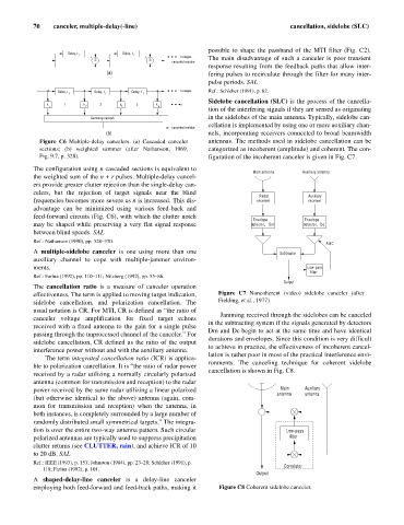
Sidelobe cancellation (SLC) is the process of the cancella-
k 1 k 2 2 k 3 3 k n
1 4
tion of the interfering signals if they are sensed as originating
Summing network in the sidelobes of the main antenna. Typically, sidelobe can-
cellation is implemented by using one or more auxiliary chan-
canceled residue
(b) nels, incorporating receivers connected to broad beamwidth
Figure C6 Multiple-delay cancelers. (a) Cascaded canceler antennas. The methods used in sidelobe cancellation can be
sections; (b) weighted summer (after Nathanson, 1969, categorized as incoherent (amplitude) and coherent. The con-
Fig. 9.7, p. 328). figuration of the incoherent canceler is given in Fig. C7.
The configuration using n cascaded sections is equivalent to
Main antenna Auxiliary antenna
the weighted sum of the n + r pulses. Multiple-delay cancel-
ers provide greater clutter rejection than the single-delay can-
celers, but the rejection of target signals near the blind
Radar Auxiliary
frequencies becomes more severe as n is increased. This dis- receiver receiver
advantage can be minimized using various feed-back and
feed-forward circuits (Fig. C6), with which the clutter notch
Envelope Envelope
may be shaped while preserving a very flat signal response detector, Dm detector, Dc
between blind speeds. SAL
Ref.: Nathanson (1990), pp. 328–330.
AGC
A multiple-sidelobe canceler is one using more than one Subtractor
auxiliary channel to cope with multiple-jammer environ-
ments. Low-pass
filter
Ref.: Farina (1992), pp. 110–111; Nitzberg (1992), pp. 55–86.
Output
The cancellation ratio is a measure of canceler operation
effectiveness. The term is applied to moving target indication, Figure C7 Noncoherent (video) sidelobe canceler (after
sidelobe cancellation, and polarization cancellation. The Fielding, et al., 1977).
usual notation is CR. For MTI, CR is defined as “the ratio of
Jamming received through the sidelobes can be canceled
canceler voltage amplification for fixed target echoes
in the subtracting system if the signals generated by detectors
received with a fixed antenna to the gain for a single pulse
Dm and Dc begin to act at the same time and have identical
passing through the unprocessed channel of the canceler.” For
durations and envelopes. Since this condition is very difficult
sidelobe cancellation, CR defined as the ratio of the output
to achieve in practice, the effectiveness of incoherent cancel-
interference power without and with the auxiliary antenna.
lation is rather poor in most of the practical interference envi-
The term integrated cancellation ratio (ICR) is applica-
ronments. The canceling technique for coherent sidelobe
ble to polarization cancellation. It is “the ratio of radar power
cancellation is shown in Fig. C8.
received by a radar utilizing a normally circularly polarized
antenna (common for transmission and reception) to the radar
power received by the same radar utilizing a linear polarized Main Auxiliary
antenna antenna
(but otherwise identical to the above) antenna (again, com-
mon for transmission and reception) when the antenna, in
both instances, is completely surrounded by a large number of
randomly distributed small symmetrical targets.” The integra-
tion is over the entire two-way antenna pattern. Such circular Low-pass
polarized antennas are typically used to suppress precipitation filter
clutter returns (see CLUTTER, rain), and achieve ICR of 10
to 20 dB. SAL
Ref.: IEEE (1993), p. 153; Johnston (1984), pp. 23–28; Schleher (1991), p.
Correlator
118; Farina (1992), p. 101.
Output
A shaped-delay-line canceler is a delay-line canceler
employing both feed-forward and feed-back paths, making it Figure C8 Coherent sidelobe canceler.