
Page 83 - Radar Technology Encyclopedia
P. 83
CRT with electrostatic focusing CENTROIDING 73
between the deflecting plates and the extent of the deflecting attempted, based on a threshold established by the surround-
field, and inversely proportional to the accelerating voltage. ing reference cells.
For this reason, to increase the brightness of the spot on the
The volume cell V is the volume within which the targets are
c
screen with small deviating voltages and short tube length,
not resolved. For specified azimuth beamwidth q elevation
a
CRTs with postacceleration are used. The beam is deflected at
beamwidth q and processed pulse width,t:
e
n
some intermediate value of the accelerating voltage, after
which the accelerating voltage reaches its full value. Rq a Rq e t c
n
V = --------- ´ --------- ´ --------
CRTs with electrostatic deflection provide wider band- c L p L p 2
width compared with CRTs with electromagnetic deflection. where R is the target range, c is the velocity of light and
This determines the primary use for displaying rapidly chang- L = 1.33 is the beamshape loss. SAL
p
ing processes. Such tubes are typically used for the smaller,
Ref.: Nathanson (1969), p. 69; Barton (1988), p. 38.
deflection-modulated CRTs (e.g., A-scopes). (See DISPLAY,
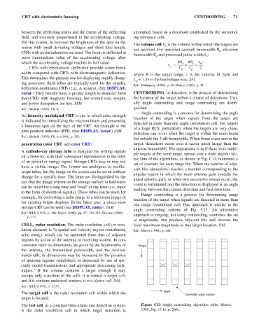
radar.) They usually have a greater length-to-diameter ratio CENTROIDING, in detection, is the process of determining
than CRTs with magnetic focusing, but overall size, weight, the location of the target within a cluster of detections. Usu-
and power dissipation are less. IAM ally angle centroiding and range centroiding are distin-
Ref.: Skolnik (1970), Ch. 6. guished.
Angle centroiding is a process for determining the angle
An intensity-modulated CRT is one in which echo strength
location of the target when signals from the target are
is indicated by intensifying the electron beam and presenting
detected in more than one angle (resolution) cell. For targets
a luminous spot on the face of the CRT. An example is the
of a large RCS, particularly when the targets are very close,
plan-position indicator (PPI). (See DISPLAY, radar.) IAM
detection can occur when the target is within the main beam
Ref.: Skolnik (1970), Ch. 6, (1980), p. 353.
but outside the 3-dB beamwidth. When beam scans across the
penetration color CRT (see color CRT). target, detections occur over a sector much larger than the
antenna beamwidth. The appearance is as if there were multi-
A cathode-ray storage tube is designed for writing signals
ple targets at the same range, spread over a wide angular sec-
on a dielectric with their subsequent reproduction in the form
tor. One of the algorithms, as shown in Fig. C13, maintains a
of an optical or energy signal. Storage CRTs may or may not
set of counters for each range bin. When the number of adja-
have a visible image. The former are analogous to oscillo-
cent hits (detections) reaches a number corresponding to the
scope tubes, but the image on the screen can be saved without
angular region in which the main antenna gain exceeds the
change for a specific time. The latter are distinguished by the
guard antenna gain, or when two successive misses occur, the
fact that the image written on the storage surface in half-tones
count is terminated and the detection is displayed at an angle
can be saved for a long time and “read” at any time (i.e., input
midway between the current detection and first detection.
in the form of electrical signals). These tubes can be used, for
Range centroiding is a process for determining range
example, for converting a radar image to a television image or
location of the target when signals are detected in more than
for creating bright displays. In the latter case, a direct-view
one range (resolution) cell. One approach is similar to the
storage CRT can be used (see DISPLAY, radar). IAM
angle centroiding scheme of Fig. C13. An alternative
Ref.: IEEE (1993), p. 166; Popov (1980), pp. 97, 130, 312; Skolnik (1980),
approach to ranging, not using centroiding, examines the set
p. 357.
of magnitudes that produce adjacent hits and chooses the
CELL, radar resolution. The radar resolution cell (or reso- local maximum magnitude as true target location. SAL
lution element) is “a spatial and velocity region contributing Ref.: Morris (1988), p. 266.
echo energy which can be separated from that of adjacent
regions by action of the antenna or receiving system. In con-
ventional radar its dimensions are given by the beamwidths of Range
the antenna, the transmitted pulsewidth, and the receiver
bandwidth; its dimensions may be increased by the presence
of spurious regions (sidelobes), or decreased by use of spe-
cially coded transmissions and appropriate processing tech-
niques.” If the volume contains a target (though it may
occupy only a portion of the cell), it is termed a target cell,
and if it contains undesired scatters, it is a clutter cell. SAL
Ref.: IEEE (1993), p. 1,133.
Angle
The target cell is the radar resolution cell within which the Centroided angle location
target is located.
The test cell, in a constant-false-alarm-rate detection system, Figure C13 Angle centroiding algorithm (after Morris,
is the radar resolution cell in which target detection is 1988, Fig. 13.11, p. 266).