
Page 86 - Radar Technology Encyclopedia
P. 86
76 chart, range-height-angle circuit, linear
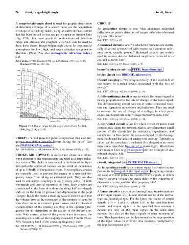
A range-height-angle chart is used for graphic description CIRCUIT
of detection coverage of a search radar (or the acquisition
An anticlutter circuit is one “that attenuates undesired
envelope of a tracking radar), using an earth surface contour
reflections to permit detection of targets otherwise obscured
that has been curved so that ray paths appear as straight lines
by such reflections.”
(Fig. C16). For most practical combinations of detection
Ref.: IEEE (1993), p. 45.
range and altitude, the program VCCALC can be used to
draw these charts. Range-height-angle charts for exponential A balanced circuit is one “in which two branches are electri-
atmosphere for low, high, and space altitudes are given in cally alike and symmetrical with respect to a common refer-
Morchin (1993). (See also atmospheric refractive index.) ence point, usually ground.” Balanced circuits are widely
SAL used in various devices: balanced amplifiers, balanced mix-
ers, and so forth. IAM
Ref. Fielding (1988); Skolnik (1990), p. 2.45; Barton (1991), pp. 8–17;
Morchin (1993), pp. 307–312. Ref.: IEEE (1993), p. 87; Popov (1980), p. 45.
beam-forming circuit (see FEED, beam-forming).
bridge circuit (see BRIDGE, microwave).
Circuit damping is “the temporal decay of the amplitude of
oscillations in a tuned circuit associated with the loss of
energy.”
Ref.: IEEE (1993), p. 302; Popov (1980), p. 131.
A differentiating circuit is one in which the output signal is
nearly proportional to the rate of change of the input signal.
The differentiating circuit consists of series-connected resis-
tors and capacitors or resistors and inductors. They are used
to measure the rate of change of a voltage, to select pulse
edges, and to perform other voltage transformations. IAM
Ref.: IEEE (1993). p. 347; Popov (1980), p. 116.
A distributed circuit is one for which circuit elements exist
Figure C16 Radar range-height-angle chart (from Skolnik,
continuously along the network; that is, any elementary small
1990, Fig. 2.18, p. 2.45)
portion of the circuit has its resistance, capacitance, and
inductance. In this circuit the areas occupied by electromag-
CHIRP is “a technique for pulse compression that uses fre- netic fields and the areas of energy loss overlap. Typically, a
quency modulation (usually linear) during the pulse” (see circuit can be considered distributed if its dimension are more
also WAVEFORMS, radar.) than some specified fraction of a wavelength. Microwave
Ref.: IEEE (1993), p. 184; Johnston (1979), p. 56; Wehner (1987), p. 127. transmission lines (e.g., waveguide) are one example of dis-
tributed circuits. SAL
CHOKE, MICROWAVE. A microwave choke is a micro-
wave element of the transmission line used as a large induc- Ref.: IEEE (1993), p. 375.
tive resistor. The choke is constructed in the form of multiple- circuit, integrated (see INTEGRATED circuit).
turn pellicular spirals of various shapes (with an inductance
An integrating circuit has an output signal that varies in pro-
of up to 100 nH) in integrated circuits. In waveguides, chokes
portion to the integral of the input signal. Integrating circuits
are typically used to prevent the energy in a specified fre-
are used to extend pulses, to smooth (filter) signals, to obtain
quency range from taking an undesired path. They are also
linearly varying voltages, to create delay in the triggering of
used in contactless couplings (usually rotary joints) of both
electronic circuits, and for other purposes. IAM
waveguide and coaxial transmission lines. Such chokes are
Ref.: IEEE (1993), p. 663; Popov (1980), p. 158.
constructed in the form of a short-circuiting half-wavelength
stub, or in the form of grooves and depressions at the joint A linear circuit is a circuit performing linear transformations
x
(flange). Inside the choke a standing wave is formed such that of the input signals (t). Linear circuits can be of the inertia-
the voltage drop at the resistance of the contacts is equal to type and inertialess-type. For the latter, the vector of output
k
x
k
y
zero, there are no microwave power losses, and the electrical signals (t) = (t)× (t), where (t) is the time-functions
characteristics of the rotating coupling at the operating fre- matrix, and output signals in the specified time moment t
quency are not dependent on the quality of the friction con- depend not only on the input signals in the same time
tacts. With correct values of the groove wave resistance, the moment, but also on the input signals in other moments of
traveling-wave ratio of the coupling exceeds 0.9 in the 50-to- time. This dependence can be determined as the superposition
70% frequency band of the operating frequency. IAM of the input values in different time moments multiplied by
the impulse response h(t)
Ref.: IEEE (1993), p. 184; Ridenour (1947), p. 396; Gassanov (1988) p. 65;
Sazonov (1988) p. 53.