
Page 81 - Radar Technology Encyclopedia
P. 81
cancellation, sidelobe (SLC) canceler, single-delay(-line) 71
A portion of the signal from the auxiliary antenna is Implementation schemes for sidelobe cancelers are usually
coherently subtracted from the main channel. The correlator categorized as closed-loop techniques (e.g., the Howells-
is used to look for a component of the main channel output, Applebaum canceler) and open-loop (or direct solution) tech-
which correlates with the output of the auxiliary channel, and niques (e.g., the Gram-Schmidt canceler). The closed-loop
the weight of the coupling from the auxiliary to the main technique is simpler and less costly than the open-loop one,
channel is changed until there is no longer any correlated out- but the latter has better speed of convergence and stability.
put. Then the combined pattern of the antennas has a null at Recently a third group of methods (data-domain or voltage-
the jammer location, which moves automatically as the main domain methods) has been developed. They are similar to the
antenna scans its sidelobes through the jammer position open-loop techniques but do not require estimating and
(Fig. C9). Two distinct ways of forming the auxiliary chan- inverting the covariance matrix for data. SAL
nels are called element space SLC and beam space SLC. Ref.: IEEE (1993), p. 1217; Farina (1992), pp. 95–216; Nitzberg (1992),
pp. 41–105.
The sidelobe canceler-blanker system is a combination of a
sidelobe blanker, for jamming of low duty factor, and a side-
lobe canceler, for jamming of high duty factor, using the same
auxiliary antenna and receiving preamplifier. A block dia-
gram of combined SLC-SLB system is shown in Fig. C10.
SAL
Ref.: Barton (1988), p. 369; (1991), p. 12-10; 172–189; Nitzberg (1992),
pp. 46–53; Maksimov (1979), pp. 172–189; Cantafio (1989), p. 456.
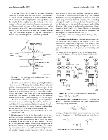
Figure C9 Patterns of radar antenna with sidelobe canceler
(from Cantafio, 1989, p. 457).
Sidelobe cancellation with beam space implementation
refers to a way of forming the auxiliary channel when the
auxiliary antenna (antennas) form a beam (beams) in the
direction of the individual jammers and the beam-formed out-
puts are sent into individual receivers, where SLC auxiliary
outputs are formed. The beam space SLC implementation Figure C10 Combined sidelobe canceler and blanker (from
perturbs the main antenna’s quiescent sidelobes less than does Barton, 1988, Fig. 7.5.4, p. 371).
an element space SLC, but its complexity and cost are higher.
Sidelobe cancellation with element space implementa- A single-delay(-line) canceler employs only one delay line
tion refers to a way of forming the auxiliary channel when (Fig. C11). Its improvement factor, for clutter centered in the
individual elements or a cluster of elements are sent through a notch, is given by the formula
receiver, and, thereafter, this output forms an auxiliary chan- f r 2 v b 2
æ
æ
nel into whichever SLC scheme is implemented. SAL I = 2 ------------ ö = 2 ------------ ö
2
2ps ø
è
2ps ø
è
c v
Ref.: Fielding, J. G., et al., Radar-77, London, 25-28 Oct. 1977, pp. 212–217;
Skolnik (1990), p. 9.11.
where f is the pulse repetition frequency, s is the rms clutter
r
c
A sidelobe canceler is the device that employs one or more spread in frequency, v is the blind speed, and s is the rms
v
b
auxiliary antennas and receivers to allow linear subtraction of
interfering signals from the desired output if they are sensed Input Output
to originate in the sidelobes of the main antenna. The tech-
nique uses the same antenna-and-receiver configuration as
Delay
the sidelobe blanker, except that a gain-matching and -cancel- line
ing process takes place. A sidelobe canceler using more than
one auxiliary channel is termed a multiple-sidelobe canceler. Figure C11 Single-delay MTI canceler.