
Page 76 - Radar Technology Encyclopedia
P. 76
66 bridge, circular bridge, waveguide
of operating frequencies in a circular bridge usually does not
exceed 20%. IAM
Ref.: Sokolov (1984), p. 136; Gardiol (1984), p. 284.
Output
l/4 3
3 /4 a a
l
Input
2
l/4 1 2
Figure B8 Slotted-waveguide bridge.
4
Output
The transmission-cavity bridge is the simplest microwave
l /4 1
bridge used for noise cancellation in continuous-wave radar.
Input
It employs the properties of transmission and reflection cavi-
Figure B6 Circular bridge.
ties (Fig. B9). The disadvantage of this configuration com-
pared with the Marsh and Wiltshire bridge is that the carrier
A Marsh and Wiltshire bridge is a microwave bridge using frequency is not suppressed before reaching the mixer. SAL
a balancing element to match the reflections from a resonant
Ref.: Skolnik (1990), p. 14.9.
cavity in such a way as to cancel the applied carrier, thereby
avoiding saturation of a mixer (Fig. B7). It is used in continu- Transmission
ous-wave radar in a noise cancellation circuit to recover the cavity I Q
noise sidebands of the input carrier so that they may be detector detector
AM
removed from the transmitted signal. SAL Microwave
source
Ref.: Skolnik (1990), p. 14.10.
p
/2
Phase
Out
shifter
Variable Variable
Amplifier
Servo
Cavity
Magic
T attenuator short
(a) In Figure B9 Transmission bridge, video version (after Skolnik,
1990, Fig. 14.3, p. 14.9).
Bridge
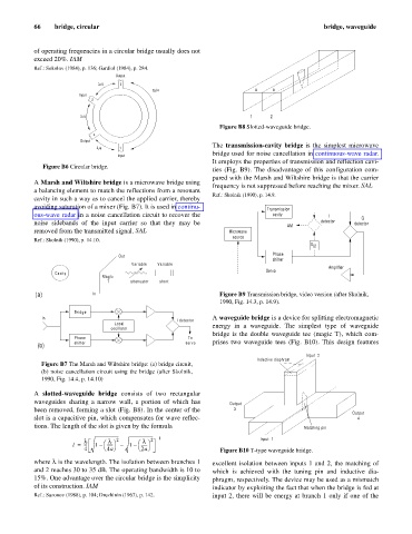
In A waveguide bridge is a device for splitting electromagnetic
I detector
Local energy in a waveguide. The simplest type of waveguide
oscillator
bridge is the double waveguide tee (magic T), which com-
Phase To
shifter servo prises two waveguide tees (Fig. B10). This design features
(b)
Input 2
Inductive diaphram
Figure B7 The Marsh and Wiltshire bridge: (a) bridge circuit,
(b) noise cancellation circuit using the bridge (after Skolnik,
1990, Fig. 14.4, p. 14.10)
A slotted-waveguide bridge consists of two rectangular
waveguides sharing a narrow wall, a portion of which has Output
been removed, forming a slot (Fig. B8). In the center of the 3
Output
slot is a capacitive pin, which compensates for wave reflec- 4
tions. The length of the slot is given by the formula Matching pin
– 1 Input 1
l l 2 l 2
l = --- 1 – æ ------ ö – 1 – æ ------ ö
4 è 4a ø è 2a ø Figure B10 T-type waveguide bridge.
where l is the wavelength. The isolation between branches 1 excellent isolation between inputs 1 and 2, the matching of
and 2 reaches 30 to 35 dB. The operating bandwidth is 10 to which is achieved with the tuning pin and inductive dia-
15%. One advantage over the circular bridge is the simplicity phragm, respectively. The device may be used as a mismatch
of its construction. IAM indicator by exploiting the fact that when the bridge is fed at
Ref.: Sazonov (1988), p. 104; Druzhinin (1967), p. 142. input 2, there will be energy at branch 1 only if one of the