
Page 78 - Radar Technology Encyclopedia
P. 78
68 calibration, mixed canceler, double-delay
where v and v are the voltages out of the receiver due to Russian literature, delay cancelers are usually termed interpe-
cal
un
the returns from the unknown and the calibration targets cor- riod cancelers.
respondingly, R and R are ranges to the unknown target Jamming cancellation is usually aimed at suppression of
cal
un
and the calibration reflector correspondingly, and s is the interfering signals received through the antenna sidelobes
cal
RCS of the calibration reflector. SAL and, thus, is the sidelobe cancellation (SLC) procedure utiliz-
Ref.: Currie and Brown (1987), p. 701. ing sidelobe cancellation algorithms. The methods of such
cancellation can be either incoherent (amplitude) or coherent.
Phase calibration is the technique in radar reflectivity mea-
Of the many sidelobe cancellation methods, Gram-Schmidt
surement that is required for coherent systems to ensure phase
and Howells-Applebaum cancelers are the classic ones.
linearity and stability. SAL
SAL
Ref.: Currie and Brown (1987), p. 763.
Ref.: IEEE (1993), p. 153; Skolnik (1962), p. 119; Maksimov (1979),
Polarization calibration is the technique in radar reflectivity pp. 172–220.
measurement involving the calibration of the polarization
A band-partitioned canceler is a technique for compensa-
matrix elements. Typically, the process involves the measure-
tion of channel frequency response between the main and
ment of polarization isolation of the system and the use of
auxiliary channels used in sidelobe cancellation. SAL
several types of calibration targets to calibrate the various
Ref.: Cantafio (1989), p. 469.
components of the polarization matrix. One of the best tech-
niques for fully polarimetric system is the polarization distor- cascaded canceler (see multiple-delay canceler).
tion method. SAL A delay-line canceler is the device used in MTI and pulse
Ref.: Currie (1987), pp. 70–72; Currie (1990), pp. 765–768. doppler radars to reject clutter echoes. Functionally, a can-
Relative calibration is the technique in radar reflectivity celer delays a copy of the input pulse train by one interpulse
measurement that defines the relationship between receiver period and then subtracts the copy from the original. Clutter
input power and output voltage (analog or converted to digital (stationary) echoes are canceled because they do not vary
form). This relationship is known as the receiver transfer from pulse to pulse, and moving targets are not canceled.
function. The process of relative calibration typically is per- Thus, the delay-line canceler performs as a filter. Its fre-
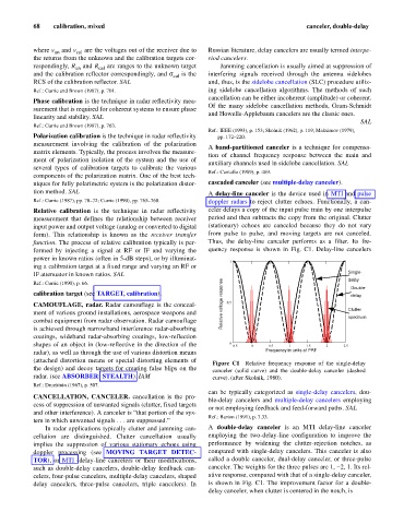
formed by injecting a signal at RF or IF and varying the quency response is shown in Fig. C1. Delay-line cancelers
power in known ratios (often in 5-dB steps), or by illuminat-
1
ing a calibration target at a fixed range and varying an RF or
IF attenuator in known ratios. SAL Single-
Ref.: Currie (1990), p. 66. delay
Double-
calibration target (see TARGET, calibration). delay
CAMOUFLAGE, radar. Radar camouflage is the conceal- Relative voltage response 0.5 Clutter
ment of various ground installations, aerospace weapons and spectrum
combat equipment from radar observation. Radar camouflage
is achieved through narrowband interference radar-absorbing
coatings, wideband radar-absorbing coatings, low-reflection
shapes of an object in (low-reflective in the direction of the 0 0.5 0 0.5 1 1.5 2 2.5
radar), as well as through the use of various distortion means Frequency in units of PRF
(attached distortion means or special distorting elements of
Figure C1 Relative frequency response of the single-delay
the design) and decoy targets for creating false blips on the canceler (solid curve) and the double-delay canceler (dashed
radar. (see ABSORBER; STEALTH). IAM curve). (after Skolnik, 1980).
Ref.: Druzhinin (1967), p. 507.
can be typically categorized as single-delay cancelers, dou-
CANCELLATION, CANCELER. cancellation is the pro-
ble-delay cancelers and multiple-delay cancelers employing
cess of suppression of unwanted signals (clutter, fixed targets
or not employing feedback and feed-forward paths. SAL
and other interference). A canceler is “that portion of the sys-
Ref.: Barton (1991), p. 7.33.
tem in which unwanted signals . . . are suppressed.”
In radar applications typically clutter and jamming can- A double-delay canceler is an MTI delay-line canceler
cellation are distinguished. Clutter cancellation usually employing the two-delay-line configuration to improve the
implies the suppression of various stationary echoes using performance by widening the clutter-rejection notches, as
doppler processing (see MOVING TARGET DETEC- compared with single-delay cancelers. This canceler is also
TOR), or MTI (delay-line cancelers or their modifications, called a double canceler, dual-delay canceler, or three-pulse
such as double-delay cancelers, double-delay feedback can- canceler. The weights for the three pulses are 1, -2, 1. Its rel-
celers, four-pulse cancelers, multiple-delay cancelers, shaped ative response, compared with that of a single-delay canceler,
delay cancelers, three-pulse cancelers, triple cancelers). In is shown in Fig. C1. The improvement factor for a double-
delay canceler, when clutter is centered in the notch, is