
Page 82 - Radar Technology Encyclopedia
P. 82
72 canceler, single-delay(-line) CRT with electrostatic focusing
velocity spread of the clutter. (See CLUTTER spectrum.) A color CRT is a one for the display of information in color.
Ref.: Barton (1964), p. 212; Currie (1987), pp. 640, 739. As applied to radar, target altitude, cross section, clutter inten-
sity, and other parameters might be color coded to provide an
three-pulse canceler (see double-delay canceler).
additional dimension for the display of target and environ-
A triple canceler is a cascaded configuration of delay-line mental information. One configuration is a penetration color
cancelers employing three delay lines, each connected as a CRT using a multilayer screen. The color is controlled by the
single canceler. It is also called a four-pulse canceler. SAL anode voltage, which determines the depth of penetration of
Ref.: Skolnik (1980), pp. 110, 135. the electron beam into a series of phosphor layers. This
method of color excitation permits better resolution than that
CAPACIVITY (see DIELECTRIC constant).
obtained with conventional TV color tubes, which explains its
CAPTURE EFFECT. The capture effect is “the tendency of interest for radar applications. SAL
a receiver to suppress the weaker of two time-coincident sig- Ref.: Skolnik (1980), pp. 353–359.
nals within its passband.”
A deflection-modulated CRT displays echo signals by
Ref.: IEEE (1993), p. 158.
deflection of the electron beam (e.g., the A-scope display).
A CARCINOTRON is a type of backward-wave tube using See DISPLAY, radar.
a nonreentrant injected beam that interacts with a traveling Ref.: Skolnik (1970), Ch. 6, (1980), p. 353.
wave in a dispersive backward-wave circuit. M-carcinotron
direct-view storage CRT (see cathode-ray storage tube).
and O-carcinotron types are distinguished. The typical fre-
quency range is between P- and K -band, CW power is A cathode-ray tube with dual deflection uses simultaneous
u
greater than 100W. The primary use is for noise-jamming sig- magnetic and electrostatic deflection systems. Magnetic
nal sources in electronic countermeasures equipment. SAL deflection shifts the beam to a specific point on the screen,
and electrostatic provides small deflections at small angles.
Ref.: Skolnik (1970), p. 7.19; Popov (1980), p. 170.
Thanks to this design, the CRT makes it possible to write
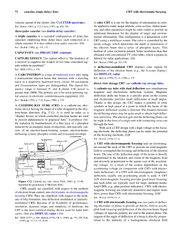
A CATHODE-RAY TUBE (CRT) is a cathode-ray elec- symbols at high speed at a point to which the beam of the
tronic device having the shape of a tube elongated in the elec- magnetic deflection system is directed. The distance between
tron-beam direction (Fig. C12). It is used in radar as a the deflecting plates may be quite small to obtain high deflec-
“display device, in which controlled electron beams are used tion sensitivity. The electron gun and the deflecting plates can
to present alphanumeric or graphical data.” It produces visi- be made in the form of a single unit with connecting wires run
ble radiation by bombardment of a thin layer of a phosphor through the base.
material by an energetic beam of electrons, and typically con- With such a CRT design with a high voltage in the focus-
sists of an electron-beam-forming system, electron-beam- ing electrode, the deflecting plates can be under the potential
deflecting system, phosphor screen and evacuated envelope. of the focusing electrode. IAM
Ref.: Skolnik (1970), Ch. 6.
A CRT with electromagnetic focusing uses an electromag-
net around the neck of the CRT to provide an axial magnetic
field to accomplish the focusing and deflection of the electron
beam. The sine of the deflection angle of the beam is directly
proportional to the intensity and extent of the magnetic field
and inversely proportional to the square root of the accelerat-
ing voltage. As a result of the weaker dependence on the
accelerating voltage (in comparison with CRTs with electro-
static deflection), in a CRT with electromagnetic (magnetic)
deflection, usually one accelerating anode is used. A CRT
with electromagnetic focusing provides good beam focusing,
Figure C12 Cathode-ray tube (from Fink, 1982, p. 11.49,
and such tubes are typically used for large, intensity-modu-
reprinted by permission of McGraw-Hill).
lated CRTs (e.g., plan position indicators). CRTs with electro-
CRTs usually are classified, with respect to the methods
magnetic focusing are relatively insensitive and require more
of electron-beam control, into electrostatic or electromagnetic
drive power than CRTs with electrostatic focusing. IAM
focusing CRTs. They are classified, with respect to the meth-
Ref.: Skolnik (1970), Ch. 6.
ods of blip formation, into deflection-modulated or intensity-
modulated CRTs. Because of its flexibility of performance, A CRT with electrostatic focusing uses two pairs of deflect-
resolution, dynamic range, and simplicity of hardware, the ing electrodes or plates to provide an electric field to accom-
CRT is the most common display device used for radar indi- plish both focusing and deflection of the electron beam. Equal
cators. (See also DISPLAY, radar.) SAL voltages of opposite polarity are sent to the paired plates. The
tangent of the angle of deflection of a beam is directly propor-
Ref.: IEEE (1993), p. 166; Skolnik (1970), Ch. 6, (1980), pp. 353–359; Fink
(1982), pp. 11.3–11.45, 25.84. tional to the intensity of a homogeneous electrical field