
Page 73 - Radar Technology Encyclopedia
P. 73
beam, cosecant-squared beams, stacked 63
introducing target amplitude scintillation as an additional
G m G m
G = ----------------------------- ³ ------- source of tracking error and reducing the subclutter visibility
c 2 – q cot q 2
1 2
in MTI or pulse-doppler radars. The most frequently used
2
Thus, the provision of csc coverage introduces a loss not technique is amplitude monopulse, which gives minimum
greater than 3 dB in the gain of a fan-beam antenna having ambiguities and sidelobe levels.
given half-power widths. DKB, SAL Beam splitting can be accomplished manually, e.g.,
Ref.: Skolnik (1980), p.259; Barton (1988), p. 26. through visual interpolation of the target displayed on a PPI,
or automatically through digital detecting the output of a
h
q q binary integrator. Beam splitting in this sense then amounts to
2 1
determining the center of a group of n pulses. This process
2
csc beam can be applied to the measurement of target range and doppler
h
m as well, which for historical reasons, is still referred to as
beam-splitting. PCH, SAL
Ref.: Skolnik (1962), pp.448, 449.
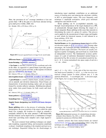
q Stacked beams are the simultaneous beams formed at differ-
Fan beam
ent elevation angles in a 3D surveillance radar. Among other
R advantages, the technique provides simultaneous lobing for
target elevation-angle estimation. The beams are usually con-
tiguous or partly overlapping, and each beam in a stack feeds
R m
an independent receiver. The fundamental accuracy perfor-
Figure B3 Cosecant-squared beam coverage for air search radar.
mance of a pair of uniformly illuminated stacked beams is
presented in Fig. B4, in terms of a normalized sensitivity fac-
difference beam (see PATTERN, difference). tor k = Kl/L versus normalized sine-space angle-of-arrival u
beam-forming (see FEED, antenna). = L/lsinq, where
·
x g
A fan beam is one that is narrow in one coordinate and wide 1
K = -----------------
in the other. As opposed to a pencil beam it provides greater 1 + f 2
scan coverage for a given scan time, at the expense of reduced
and f = f(q) = G (q)/G (q) is the ratio of the two-way eleva-
2
1
gain (see ANTENNA, fan-beam). SAL
tion beam power patterns, f = df /dq, g is the two-way nor-
1
Ref.: Johnson (1993), p. 1.13; Skolnik (1980), p. 55.
malized voltage pattern in beam position one, L is the
interrogation beam (see RADAR, secondary surveillance). aperture dimension, l is wavelength, and q is elevation angle.
In the figure, Du is u-space beam separation.
A pencil beam is a narrow antenna beam, usually symmetri-
cal in azimuth and elevation dimensions. Pencil beams are
characteristic of precision-tracking radars and are typically
formed by circular reflector antennas. Multifunction phased-
array radars form pencil beams for both search and track.
PCH
Ref.: Johnson (1993), p. 1.13; Skolnik (1980), p. 55.
beam pattern (see PATTERN).
beamshape loss (see LOSS, beamshape).
doppler beam sharpening (see DOPPLER beam sharpen-
ing).
Beam splitting refers to the process of estimating, through
interpolation, the exact position of the target within the radar
beam. For example, the location of a target in azimuth is
nominally defined by the radar antenna’s 3-dB beamwidth, Figure B4 Fundamental accuracy of a stacked-beam elevation
but this estimate can be improved by a combination of longer estimator (from Murrow, Fig. 20.8, p. 20.32 in Skolnik, 1990,
dwell time (providing more samples) and a high signal-to- reprinted by permission of McGraw-Hill).
noise ratio.
Antenna systems that form stacked beams are termed
The most common beam-splitting techniques are ampli-
stacked-beam antennas and corresponding radars using this
tude weighting, sequential lobing, and monopulse (amplitude
technique are called stacked-beam radars. SAL
or phase). Amplitude weighting is the simplest and least accu-
Ref.: IEEE (1993), p. 1272; Skolnik (1990), p. 20.31.
rate technique. Sequential lobing has the disadvantages of