
Page 72 - Radar Technology Encyclopedia
P. 72
62 bandwidth, narrow bandwidth assumption beam, cosecant-squared
nents with equal variance, and w is the angular frequency at and B ¢ may then be used to calculate the system matching
n
the center of the passband. DKB loss or collapsing loss to a given signal. DKB
Ref.: Cook (1967), p. 61. Barton (1993), p. 102.
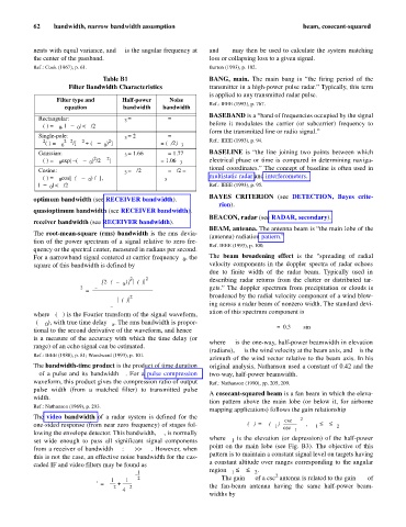
Table B1 BANG, main. The main bang is “the firing period of the
Filter Bandwidth Characteristics transmitter in a high-power pulse radar.” Typically, this term
is applied to any transmitted radar pulse. SAL
Filter type and Half-power Noise
Ref.: IEEE (1993), p. 767.
equation bandwidth bandwidth
BASEBAND is a “band of frequencies occupied by the signal
Rectangular: B = B B = B
3
n
H(f) = H , | f - f | < B/2 before it modulates the carrier (or subcarrier) frequency to
0
0
form the transmitted line or radio signal.” SAL
Single-pole: B = 2f a B = p f a
3
n
2 2 2 2 2 Ref.: IEEE (1993), p. 94.
B
H (f) = H f /[ f a + ( f - f ) ] = (p/2)
3
0 a
0
Gaussian: B = 1.66s h B = 1.77s h BASELINE is “the line joining two points between which
3
n
2
2
H(f) = H exp[- ( f - f ) /2s ] = 1.06B 3 electrical phase or time is compared in determining naviga-
h
0
0
tional coordinates.” The concept of baseline is often used in
Cosine: B = B/2 B = B/2 =
n
3
f - ) /B],
H(f) = H cos[p( f 0 B 3 multistatic radar and interferometers. SAL
0
|f - f | < B/2 Ref.: IEEE (1993), p. 95.
0
BAYES CRITERION (see DETECTION, Bayes crite-
optimum bandwidth (see RECEIVER bandwidth).
rion).
quasioptimum bandwidth (see RECEIVER bandwidth).
BEACON, radar (see RADAR, secondary).
receiver bandwidth (see RECEIVER bandwidth).
BEAM, antenna. The antenna beam is “the main lobe of the
The root-mean-square (rms) bandwidth is the rms devia-
(antenna) radiation pattern.”
tion of the power spectrum of a signal relative to zero fre-
Ref. IEEE (1993), p. 100.
quency or the spectral center, measured in radians per second.
For a narrowband signal centered at carrier frequency f , the The beam broadening effect is the “spreading of radial
0
square of this bandwidth is defined by velocity components in the doppler spectra of radar echoes
due to finite width of the radar beam. Typically used in
¥ 2 2
ò [ 2p f – f )]Sf () fd describing radar returns from the clutter or distributed tar-
(
0
2 – ¥ gets.” The doppler spectrum from precipitation or clouds is
b = -------------------------------------------------------------
¥ broadened by the radial velocity component of a wind blow-
2
ò Sf () f
d
– ¥ ing across a radar beam of nonzero width. The standard devi-
ation of this spectrum component is
where S( f ) is the Fourier transform of the signal waveform,
s(t-t), with true time delay t. The rms bandwidth is propor-
0 o s = 0.3v q sin b
tional to the second derivative of the waveform, and hence b b w e
is a measure of the accuracy with which the time delay (or
where q is the one-way, half-power beamwidth in elevation
range) of an echo signal can be estimated. DKB e
(radians), v is the wind velocity at the beam axis, and b is the
w
Ref.: IEEE (1988), p. 81; Woodward (1993), p. 101.
azimuth of the wind vector relative to the beam axis. In his
The bandwidth-time product is the product of time duration original analysis, Nathanson used a constant of 0.42 and the
tof a pulse and its bandwidth B. For a pulse compression two-way, half-power beamwidth. SAL
waveform, this product gives the compression ratio of output Ref.: Nathanson (1990), pp. 205, 209.
pulse width (from a matched filter) to transmitted pulse
A cosecant-squared beam is a fan beam in which the eleva-
width. DKB
tion pattern above the main lobe (or below it, for airborne
Ref.: Nathanson (1969), p. 293.
mapping applications) follows the gain relationship
The video bandwidth of a radar system is defined for the æ csc q ö
2
(
=
one-sided response (from near zero frequency) of stages fol- G q() G q ) -------------- , q £ q £ q 2
1
q ø
1 è
csc
lowing the envelope detector. This bandwidth, B , is normally 1
v
1
set wide enough to pass all significant signal components where q is the elevation (or depression) of the half-power
point on the main lobe (see Fig. B3). The objective of this
from a receiver of bandwidth B : B >> B . However, when
n
n
v
this is not the case, an effective noise bandwidth for the cas- pattern is to maintain a constant signal level on targets having
a constant altitude over ranges corresponding to the angular
caded IF and video filters may be found as
.
region q £ q £ q
1 1 2
– -- - 2
æ 1 1 ö 2 The gain G of a csc antenna is related to the gain G of
m
c
B ' = ç ------ + --------- ÷ the fan-beam antenna having the same half-power beam-
n
2
2
è B 4B ø
n v widths by