
Page 61 - Radar Technology Encyclopedia
P. 61
array, Yagi-Uda ATMOSPHERE 51
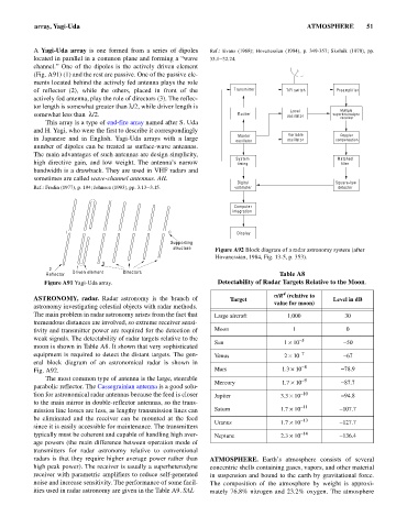
A Yagi-Uda array is one formed from a series of dipoles Ref.: Evans (1968); Hovanessian (1984), p. 349-357; Skolnik (1970), pp.
located in parallel in a common plane and forming a “wave 33.1–32.24.
channel.” One of the dipoles is the actively driven element
(Fig. A91) (1) and the rest are passive. One of the passive ele-
ments located behind the actively fed antenna plays the role
of reflector (2), while the others, placed in front of the Transmitter T/R switch Preamplifier
actively fed antenna, play the role of directors (3). The reflec-
tor length is somewhat greater than l/2, while driver length is
Local Multiple
somewhat less than l/2. Exciter oscillator superheterodyne
receiver
This array is a type of end-fire array named after S. Uda
and H. Yagi, who were the first to describe it correspondingly
Master Variable Doppler
in Japanese and in English. Yagi-Uda arrays with a large oscillator oscillator compensation
number of dipoles can be treated as surface-wave antennas.
The main advantages of such antennas are design simplicity,
System Matched
high directive gain, and low weight. The antenna’s narrow timing filter
bandwidth is a drawback. They are used in VHF radars and
sometimes are called wave-channel antennas. AIL
Digital Square-law
Ref.: Fradin (1977), p. 194; Johnson (1993), pp. 3.13–3.15. voltmeter detector
Computer
integration
Display
Supporting
structure Figure A92 Block diagram of a radar astronomy system (after
Hovanessian, 1984, Fig. 13-5, p. 353).
3
1
2
Reflector Driven element Directors Table A8
Figure A91 Yagi-Uda array. Detectability of Radar Targets Relative to the Moon.
4
s /R (relative to
ASTRONOMY, radar. Radar astronomy is the branch of Target Level in dB
astronomy investigating celestial objects with radar methods. value for moon)
The main problem in radar astronomy arises from the fact that Large aircraft 1,000 30
tremendous distances are involved, so extreme receiver sensi-
tivity and transmitter power are required for the detection of Moon 1 0
weak signals. The detectability of radar targets relative to the -5
Sun 1 ´ 10 -50
moon is shown in Table A8. It shown that very sophisticated
equipment is required to detect the distant targets. The gen- Venus 2 ´ 10 -7 -67
eral block diagram of an astronomical radar is shown in -8
Fig. A92. Mars 1.3 ´ 10 -78.9
The most common type of antenna is the large, steerable -9
Mercury 1.7 ´ 10 -87.7
parabolic reflector. The Cassegrainian antenna is a good solu-
tion for astronomical radar antennas because the feed is closer Jupiter 3.3 ´ 10 -10 -94.8
to the main mirror in double-reflector antennas, so the trans- -11
mission line losses are less, as lengthy transmission lines can Saturn 1.7 ´ 10 -107.7
be eliminated and the receiver can be mounted at the feed -13
Uranus 1.7 ´ 10 -127.7
since it is easily accessible for maintenance. The transmitters
typically must be coherent and capable of handling high aver- Neptune 2.3 ´ 10 -14 -136.4
age powers (the main difference between operation mode of
transmitters for radar astronomy relative to conventional
radars is that they require higher average power rather than ATMOSPHERE. Earth’s atmosphere consists of several
high peak power). The receiver is usually a superheterodyne concentric shells containing gases, vapors, and other material
receiver with parametric amplifiers to reduce self-generated in suspension and bound to the earth by gravitational force.
noise and increase sensitivity. The performance of some facil- The composition of the atmosphere by weight is approxi-
ities used in radar astronomy are given in the Table A9. SAL mately 76.8% nitrogen and 23.2% oxygen. The atmosphere