
Page 59 - Radar Technology Encyclopedia
P. 59
array, radio-optical array, subarray 49
The shortcoming of radio-optical arrays includes a wid- array scanning methods (see SCANNING).
ening of the beam that results in a slight decrease in direc-
A self-phased [-focusing] array is an antenna-reflector rera-
tional gain. AIL
diating the energy in the direction of the incident electromag-
Ref.: Voskresenskiy (1986), pp. 14–28; Zmuda (1994), Ch. 11.
netic wave. As opposed to the other antenna-reflectors (e.g.,
A reflectarray is a space-fed phased array in which the ele- the Van-Atta array) where array elements are coupled in pairs,
ments are illuminated from the front by a feed and reradiate a self-phasing arrays use other methods to introduce the desired
controlled phase front that produces a beam scanned relative phase shift. This may involve use of frequency conversion,
to the broadside direction (see FEED, space). where the local oscillator (LO) frequency is exactly equal to
or twice the frequency of the incidence wave and a difference
re(tro)directive array (see Van Atta array).
frequency is used; use of double frequency conversion where
A ring array is one whose radiators are placed along one or the LO frequency is close to the frequency of the incident
several rings. A disadvantage of single-ring arrays is the rela- wave; using two phase shifters, and so forth. Sometimes this
tively high sidelobe level. To reduce the sidelobes multi-ring array is termed a self-focusing array. AIL
arrays are used. Ring arrays can be constructed in the form of Ref.: Steinberg (1976), p. 214; Fradin (1977), p. 343.
a circle, ellipse, or sphere. The advantage of a ring array is its
A signal-processing array is one in which special signal pro-
ability to radiate in any direction. This array is also termed an
cessing of the received signals is used to enhance the quality
annular array. In practical radars such arrays are seldom
of extraction of information. Usually the following signal-
used. AIL
processing techniques are used: temporal modulation of the
Ref.: Benenson (1966), p. 238, Mailloux (1994), pp 197–204.
antenna parameters (see ANTENNA, space-time), logical
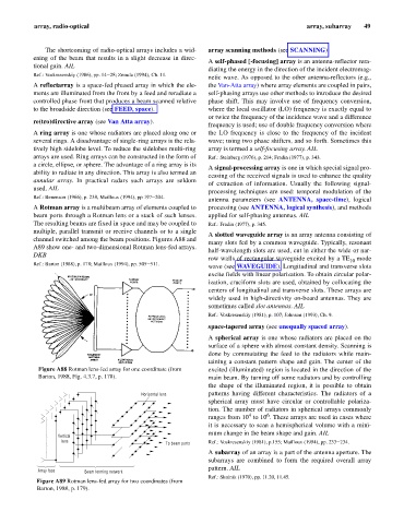
A Rotman array is a multibeam array of elements coupled to processing (see ANTENNA, logical synthesis), and methods
beam ports through a Rotman lens or a stack of such lenses. applied for self-phasing antennas. AIL
The resulting beams are fixed in space and may be coupled to Ref.: Fradin (1977), p. 345.
multiple, parallel transmit or receive channels or to a single
A slotted waveguide array is an array antenna consisting of
channel switched among the beam positions. Figures A88 and
many slots fed by a common waveguide. Typically, resonant
A89 show one- and two-dimensional Rotman lens-fed arrays.
half-wavelength slots are used, cut in either the wide or nar-
DKB
row walls of rectangular waveguide excited by a TE 10 mode
Ref.: Barton (1988), p. 178; Mailloux (1994), pp. 505–511.
wave (see WAVEGUIDE). Longitudinal and transverse slots
excite fields with linear polarization. To obtain circular polar-
ization, cruciform slots are used, obtained by collocating the
centers of longitudinal and transverse slots. These arrays are
widely used in high-directivity on-board antennas. They are
sometimes called slot antennas. AIL
Ref.: Voskresenskiy (1981), p. 107; Johnson (1993), Ch. 9.
space-tapered array (see unequally spaced array).
A spherical array is one whose radiators are placed on the
surface of a sphere with almost constant density. Scanning is
done by commutating the feed to the radiators while main-
taining a constant pattern shape and gain. The center of the
Figure A88 Rotman lens-fed array for one coordinate (from excited (illuminated) region is located in the direction of the
Barton, 1988, Fig. 4.3.7, p. 178). main beam. By turning off some radiators and by controlling
the shape of the illuminated region, it is possible to obtain
Horizontal lens patterns having different characteristics. The radiators of a
spherical array must have circular or controllable polariza-
tion. The number of radiators in spherical arrays commonly
4
6
ranges from 10 to 10 . These arrays are used in cases where
it is necessary to scan a hemispherical volume with a mini-
mum change in the beam shape and gain. AIL
Vertical
lens
To beam ports Ref.: Voskresenskiy (1981), p.155; Mailloux (1994), pp. 233–234.
A subarray of an array is a part of the antenna aperture. The
subarrays are combined to form the required overall array
pattern. AIL
Array face Beam forming network
Ref.: Skolnik (1970), pp. 11.20, 11.45.
Figure A89 Rotman lens-fed array for two coordinates (from
Barton, 1988, p. 179).