
Page 54 - Radar Technology Encyclopedia
P. 54
44 array directivity array, fiber-optic
where h is the aperture efficiency and l is the wavelength. ing elements are nonisotropic, and a radiator in the array envi-
For a two-dimensional array, ronment has a pattern that differs from the pattern of isolated
element in amplitude, phase, and sometimes in polarization
Nd d also (see mutual coupling in array). Mutual coupling results
x y
D » 4ph --------------- cos q 0
2
l in the phenomenon wherein radiator impedance varies as a
function of scanning. The selection of the radiator for particu-
d
where and d are the spacings in the two coordinates and q 0 lar array is based on the consideration of its physical dimen-
x
y
is the angle between the main beam and the normal to the sions and environmental requirements, polarization and
array surface (see also ANTENNA directivity). SAL power-handling capability, and appropriate aperture matching
Ref.: Johnson (1984), pp, 20.15, 20.22. over the required scanning range. SAL
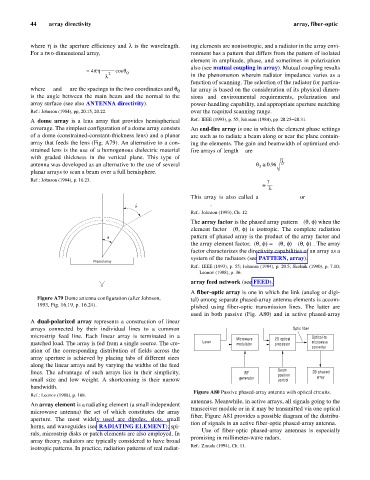
A dome array is a lens array that provides hemispherical Ref.: IEEE (1993), p. 55; Johnson (1984), pp. 20.25–20.31.
coverage. The simplest configuration of a dome array consists An end-fire array is one in which the element phase settings
of a dome (constrained-constant-thickness lens) and a planar are such as to radiate a beam along or near the plane contain-
array that feeds the lens (Fig. A79). An alternative to a con- ing the elements. The gain and beamwidth of optimized end-
strained lens is the use of a homogenous dielectric material fire arrays of length L are
with graded thickness in the vertical plane. This type of
l
antenna was developed as an alternative to the use of several q @ 0.96 ---
3
L
planar arrays to scan a beam over a full hemisphere. SAL
Ref.: Johnson (1984), p. 16.23. 7L
G @ ------
l
This array is also called a traveling-wave or surface-wave
' antenna. SAL
q
Ref.: Johnson (1993), Ch. 12.
The array factor is the phased array pattern f (q, f) when the
a
element factor f (q, f) is isotropic. The complete radiation
e
pattern of phased array is the product of the array factor and
q
f (q, f) f
the array element factor, f(q, f) = (q, f) . The array
e
a
factor characterizes the directivity capabilities of an array as a
system of the radiators (see PATTERN, array). SAL
Phased array
Ref.: IEEE (1993), p. 55; Johnson (1984), p. 20.5; Skolnik (1990), p. 7.10;
Leonov (1988), p. 36.
array feed network (see FEED).
A fiber-optic array is one in which the link (analog or digi-
Figure A79 Dome antenna configuration (after Johnson, tal) among separate phased-array antenna elements is accom-
1993, Fig. 16.19, p. 16.24). plished using fiber-optic transmission lines. The latter are
used in both passive (Fig. A80) and in active phased-array
A dual-polarized array represents a construction of linear
arrays connected by their individual lines to a common Optic fiber
microstrip feed line. Each linear array is terminated in a Microwave 2D optical Optical-to
matched load. The array is fed from a single source. The cre- Laser modulator processor microwave
converter
ation of the corresponding distribution of fields across the
array aperture is achieved by placing tabs of different sizes
along the linear arrays and by varying the widths of the feed
Beam
lines. The advantage of such arrays lies in their simplicity, RF position 2D phased
array
small size and low weight. A shortcoming is their narrow generator control
bandwidth. AIL
Figure A80 Passive phased-array antenna with optical circuits.
Ref.: Leonov (1988), p. 168.
antennas. Meanwhile, in active arrays, all signals going to the
An array element is a radiating element (a small independent
transceiver module or in it may be transmitted via one optical
microwave antenna) the set of which constitutes the array
fiber. Figure A81 provides a possible diagram of the distribu-
aperture. The most widely used are dipoles, slots, small
tion of signals in an active fiber-optic phased-array antenna.
horns, and waveguides (see RADIATING ELEMENT); spi-
Use of fiber-optic phased-array antennas is especially
rals, microstrip disks or patch elements are also employed. In
promising in millimeter-wave radars. AIL
array theory, radiators are typically considered to have broad
Ref.: Zmuda (1994), Ch. 11.
isotropic patterns. In practice, radiation patterns of real radiat-