
Page 52 - Radar Technology Encyclopedia
P. 52
42 approximation, four-thirds earth radius array bandwidth
the factor k can be expressed for arbitrary value of the gradi- ence level at the output of the array; (c) minimum interfer-
ent as ence power at the array output; or (d) the maximum
1 probability of detection of the desired target signal. AIL
k = ---------------------------
1 – k an ¤ 0 Ref.: Bakhrakh (1989), p. 167; Steinberg (1976), Chaps. 11, 12; Mailloux
1
(1994), pp. 167–186.
that results in k = 4/3 for paths at low or medium altitude in
An amplifier array is one with the final transmitter amplifier
the standard atmosphere DKB, SAL
and the first receiving amplifier placed at the array element.
Ref.: Blake (1980), p. 184.
In constrained feed systems, these amplifiers may be placed
North’s approximation (see DETECTION probability). at any level in the dividing network: at the individual radiat-
ing element, at row or column level, or at subarrays. An
The spherical earth (parabolic) approximation, used in
advantage of placing amplifiers at the element is that the
height finding, accounts for the earth’s curvature as parabolic
phase shifter may be placed on the feed side of the amplifier,
in range and gives a target height for a radar located near the
reducing its power rating and the effect of phase shifter loss
surface of the earth as
on system performance. In a typical solid-state modular array,
2
R
h = h + Rsin q + --------- a common phase shifter at each element amplifier is switched
t a t 2ka
between the transmit and receive paths, while the radiating
where a is the radius of the earth, k @ 4/3 is the factor taking element is connected to the amplifier through a circulator
into account refraction (see four-thirds earth radius (Fig. A77).
approximation) and the other parameters are defined in the
flat-earth approximation. SAL Power amplifier & driver
Ref.: Skolnik (1990), p. 20.14.
DC power
Preamplifier
ARRAY (ANTENNA). An array antenna is “an antenna driver
To
comprised of a number of identical radiating elements in a antenna
regular arrangement and excited to obtained a prescribed
radiation pattern.” The main types of array antennas used in
RF Phase Channel
radar applications are phased arrays and frequency-scanned manifold shifter T/R switch
arrays. SAL Limiter Dummy
T/R load
Ref.: IEEE (1993), p. 55. Row Low-noise switch
Column Logic amplifier
An active array is one in which an active element (oscillator, Transfer (for 5V) T/R logic
Shift
T/R No. 1
amplifier, or mixer) is connected to the path of each radiator. T/R No. 2
These elements, along with the radiator, form the array mod-
ule. Active antenna arrays are categorized as receiving, trans-
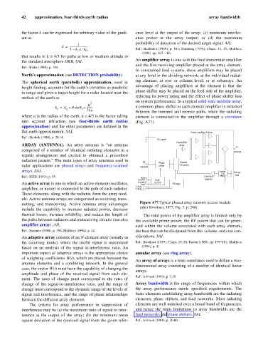
mitting, and transceiving. Active antenna array advantages Figure A77 Typical phased-array transmit-receive module
(after Brookner, 1977, Fig. 3, p. 266).
include the capability to increase radiated power, decrease
thermal losses, increase reliability, and reduce the length of The total power of the amplifier array is limited only by
the paths between radiators and transceiving circuits (see also the available prime power, the RF power that can be gener-
amplifier array). AIL ated within the volume associated with each array element,
Ref.: Sazonov (1988), p. 396; Mailloux (1994), p. 41. the heat that can be dissipated from this volume, and cost con-
An adaptive array consists of an N-element array (usually in siderations. SAL
the receiving mode), where the useful signal is maximized Ref.: Brookner (1977), Chaps. 19, 20; Barton (1988), pp. 179–181; Mailloux
based on an analysis of the signal-to-interference ratio. An (1994), p. 41.
important aspect of adaptive arrays is the appropriate choice annular array (see ring array).
of weighting coefficients W(t), which are placed between the
An array of arrays is a term sometimes used to define a two-
antenna elements and a combining network. In the general
dimensional array consisting of a number of identical linear
case, the vector W(t) must have the capability of changing the
arrays.
amplitude and phase of the received signal from each ele-
Ref.: Johnson (1993), p. 3.29.
ment. The rates of change must correspond to the rates of
change of the signal-to-interference ratio, and the range of Array bandwidth is the range of frequencies within which
change must correspond to the dynamic range of the levels of the array performance meets specified requirements. The
signal and interference, and the range of phase relationships basic elements establishing array bandwidth are the radiating
between the different array elements. elements, phase shifters, and feed networks. Most radiating
The criteria for array performance in suppression of elements are well matched over a broad band of frequencies,
interference may be (a) the maximum ratio of signal to inter- and hence the main limitations to array bandwidth are the
ference at the output of the array; (b) the minimum mean feed networks and phase shifters. SAL
square deviation of the received signal from the given refer- Ref.: Johnson (1984), p. 20.60.