
Page 55 - Radar Technology Encyclopedia
P. 55
array, fiber-optic array (aperture) matching 45
1st element nerable to jamming since a jammer can concentrate its energy
Transmitter Microwave
reference generator over a narrow frequency band. The most practical solution
signal
lies in frequency agility when a multiple-beam-forming net-
Detector
LO work is used with multiple interleaved arrays. See also
reference Laser LO
signal RADAR, frequency-scan; PATTERN, antenna. SAL
Ref.: Johnson (1984), p. 19.1; Skolnik (1980), p. 298; Voskresenskiy (1981),
Control Control p. 64.
A linear array is one consisting of a group of identical ele-
ments placed in one dimension along a given direction. Lin-
Monitor
Laser ear arrays may have equidistant or nonequidistant element
Monitor Detector
spacings. They are used in the analysis of the directional
Receiver
properties of arrays in antenna theory (see PATTERN,
Signal
processing array), and as building blocks for forming an array of arrays.
2nd element
AIL
Nth element
Ref.: Venenson (1966), p. 72; Mailloux (1994), pp. 72–81; Johnson (1993),
Figure A81 Signal distribution in an active fiber-optic phased- pp. 3.1–3.29, 20.3–20.15.
array antenna.
A low-sidelobe array is one for which the antenna sidelobe
level is maintained below some specified level (see
A frequency-scan array is one “in which the direction of the
ANTENNA, low-sidelobe). Since for phased arrays the
radiated beam is controlled by changing of the operating fre-
amplitude of each element can be controlled individually,
quency.” The frequency scan principle is based on the fact
good sidelobe control in comparison with reflector antennas
that the change of frequency produces a change in phase of
can be achieved. The sidelobe reduction is achieved at the
the signal passing through the length of a transmission line
expense of gain reduction and increased beamwidth. It also
(see SCANNING, frequency). Typically, the array is passive
increases the cost of the antenna and the complexity of toler-
radiators are excited directly from the beam-forming network.
ance control, and it imposes requirements for operation in an
Either serial or parallel feed configurations can be used. The
environment free from obstructions that would cause sidelobe
most common types of feeds are the sinuous feed (and tan-
increase. SAL
dem-sinuous feed for monopulse technique) and the dummy-
Ref.: Brookner (1988), Ch. 6; Skolnik (1990), p. 7.37.
snake feed. A practical example of frequency-scan array with
dual scan bands is the AN/SPS-48 (Fig. A82). Array (aperture) matching is the matching of the array with
its feed network and with free space. Usually wide-angle
matching is used, which allows the improvement of the char-
acteristics at all scanning sectors of the array. Methods of
wide-angle matching of a phased array can be divided into
two groups: (1) methods related to a modification of the phys-
ical construction of the array excitation and (2) methods
based on placing dummy elements in front of the array aper-
ture, whose reflection reduces the change in the output
impedance of the radiators during scanning.
Group 1 includes the following ways of wide-angle
matching:
(1) Use of connecting circuits between elements.
(2) Filling of the waveguide horns with dielectric.
The size of the waveguide horns and the parameters of the
filling medium are selected so that a wave can propagate in
only a single mode.
(3) Use of waveguide radiators with several types
of propagating modes.
Group II uses the following methods:
(1) Placing a conducting partition parallel to the E-
plane of the dipole radiators. These partitions reduce the
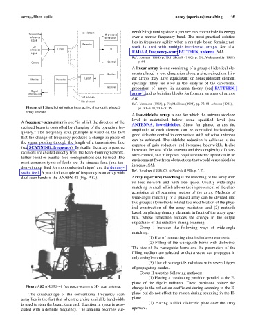
Figure A82 AN/SPS-48 frequency-scanning 3D radar antenna.
change in the reflection coefficient during scanning in the E-
The disadvantage of the conventional frequency scan plane but do not effect the match during scanning in the H-
array lies in the fact that when the entire available bandwidth plane.
is used to steer the beam, then each direction in space is asso- (2) Placing a thick dielectric plate over the array
ciated with a definite frequency. The antenna becomes vul- aperture.