
Page 31 - Rapid Learning in Robotics
P. 31
2.2 Actuation: The Hand “Manus” 17
2.2.1 Oil model
The finger joints are driven by small, spring loaded, hydraulic cylinders,
which connect each actuator to the base station by a oil hose. In contrast
to the more standard hydraulic system with a central power supply and
valve controlled bi-directional powered cylinder, here, each finger cylin-
der is one-way powered from a corresponding cylinder at the base sta-
tion. Unfortunately, the finger design does not foresee integrated sensors
directly at the fingers.
X p X
m f k
Motor
Oil Hose F
pistonExt.
κ
Base Station A m A f Finger
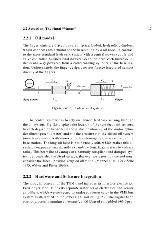
Figure 2.6: The hydraulic oil system.
The control system has to rely on indirect feedback sensing through
the oil system. Fig. 2.6 displays the location of the two feedback sensors.
In each degree of freedom i the piston position x m of the motor cylin-
der (linear potentiometer) and ii the pressure p in the closed oil system
(membrane sensor with semi-conductor strain-gauge) is measured at the
base station. The long oil hose is not perfectly stiff, which makes this oil
system component significantly expandable (4 m, large surface to volume
ratio). This bears the advantage of a naturally compliant and damped sys-
tem but bears also the disadvantage, that even pure position control must
consider the force - position coupled oil model (Menzel et al. 1993; Selle
1995; Walter and Ritter 1996c).
2.2.2 Hardware and Software Integration
The modular concept of the TUM-hand includes its interface electronics.
Each finger module has its separate motor servo electronics and sensor
amplifiers, which we connected to analog converter cards in the VME bus
system as illustrated in the lower right part of Fig. 2.2. The digital hand
control process is running at “manus”, a VME based embedded 68040 pro-