
Page 27 - Rapid Learning in Robotics
P. 27
2.1 Actuation: The Puma Robot 13
(a special thread) at a special device driver serving the interrupts from a
timer card. The control task is thus running independently and outside
the planning task. By this means, sensory information (e.g. camera or force
sensors) can be processed and feedback in a very effective and convenient
manner.
For example, by default our DLR 6 D wrist sensor is read out about the
currently exerted force and torque vector (3+3=6 D) between the robot arm
and the robot hand (Fig. 2.1, 2.4). The DLR Force-Torque-Sensor (FTS) was
developed by the robotics group of Prof. Hirzinger of the DLR, Oberpfaf-
fenhofen, and is a spin-off from the ROTEX Spacelab mission D2 (Hirzinger,
Brunner, Dietrich, and Heindl 1994). As indicated in Fig. 2.2, the FTS is
an micro-controller based sensory sub-system, which communicates via a
special field-bus with the VME-bus.
(Sun "druide") (Puma Controller)
θ meas
X des X Coordinate θ des Position Robot
1-S + - +
transform Controller
Environment
F des Force
Control S
Law
Coordinate
F F
trans transform meas
+ Gravity
Compens.
X trans Coordinate θ meas
Sensory Guard transform
Pattern
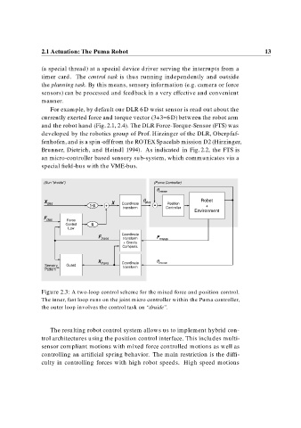
Figure 2.3: A two-loop control scheme for the mixed force and position control.
The inner, fast loop runs on the joint micro controller within the Puma controller,
the outer loop involves the control task on “druide”.
The resulting robot control system allows us to implement hybrid con-
trol architectures using the position control interface. This includes multi-
sensor compliant motions with mixed force controlled motions as well as
controlling an artificial spring behavior. The main restriction is the diffi-
culty in controlling forces with high robot speeds. High speed motions