
Page 240 - Rashid, Power Electronics Handbook
P. 240
14 Inverters 229
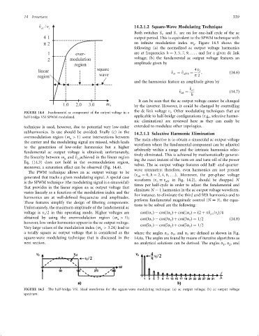
v ˆ o1 v / i 14.2.1.2 Square-Wave Modulating Technique
Both switches S and S are on for one-half cycle of the ac
þ
ÿ
4 1 output period. This is equivalent to the SPWM technique with
p 2 an in®nite modulation index m . Figure 14.5 shows the
a
following: (a) the normalized ac output voltage harmonics
1 are at frequencies h ¼ 3; 5; 7; 9; ... , and for a given dc link
2 voltage; (b) the fundamental ac output voltage features an
amplitude given by
4 v i
^ v ¼ ^ v aN1 ¼ ; ð14:6Þ
o1
p 2
and the harmonics feature an amplitude given by
^ v o1
^ v ¼ ð14:7Þ
oh
h
It can be seen that the ac output voltage cannot be changed
by the inverter. However, it could be changed by controlling
the dc link voltage v . Other modulating techniques that are
FIGURE 14.4 Fundamental ac component of the output voltage in a i
applicable to half-bridge con®gurations (e.g., selective harmo-
half-bridge VSI SPWM modulated.
nic elimination) are reviewed here as they can easily be
technique is used, however, due to potential very low-order extended to modulate other topologies.
subharmonics, its use should be avoided; ®nally (c) in the 14.2.1.3 Selective Harmonic Elimination
overmodulation region (m > 1) some intersections between
a The main objective is to obtain a sinusoidal ac output voltage
the carrier and the modulating signal are missed, which leads waveform where the fundamental component can be adjusted
to the generation of low-order harmonics but a higher arbitrarily within a range and the intrinsic harmonics selec-
fundamental ac output voltage is obtained; unfortunately,
tively eliminated. This is achieved by mathematically generat-
the linearity between m and ^ v achieved in the linear region
a o1 ing the exact instant of the turn-on and turn-off of the power
Eq. (14.3) does not hold in the overmodulation region,
valves. The ac output voltage features odd half- and quarter-
moreover, a saturation effect can be observed (Fig. 14.4).
wave symmetry; therefore, even harmonics are not present
The PWM technique allows an ac output voltage to be
(v ¼ 0; h ¼ 2; 4; 6; ...). Moreover, the per-phase voltage
generated that tracks a given modulating signal. A special case oh
waveform (v ¼ v in Fig. 14.2), should be chopped N
is the SPWM technique (the modulating signal is a sinusoidal) o aN
times per half-cycle in order to adjust the fundamental and
that provides in the linear region an ac output voltage that
eliminate N ÿ 1 harmonics in the ac output voltage waveform.
varies linearly as a function of the modulation index and the
For instance, to eliminate the third and ®fth harmonics and to
harmonics are at well-de®ned frequencies and amplitudes.
perform fundamental magnitude control (N ¼ 3), the equa-
These features simplify the design of ®ltering components.
tions to be solved are the following:
Unfortunately, the maximum amplitude of the fundamental ac
voltage is v =2 in this operating mode. Higher voltages are cosð1a Þÿ cosð1a Þþ cosð1a Þ¼ ð2 þ p^ v =v Þ=4
2
i
3
o1
1
i
obtained by using the overmodulation region (m > 1); cosð3a Þÿ cosð3a Þþ cosð3a Þ¼ 1=2 ð14:8Þ
a
1
3
2
however, low-order harmonics appear in the ac output voltage.
cosð5a Þÿ cosð5a Þþ cosð5a Þ¼ 1=2
1
3
2
Very large values of the modulation index (m > 3:24) lead to
a
a totally square ac output voltage that is considered as the where the angles a , a , and a are de®ned as shown in Fig.
1 2 3
square-wave modulating technique that is discussed in the 14.6a. The angles are found by means of iterative algorithms as
next section. no analytical solutions can be derived. The angles a , a , and
1 2
FIGURE 14.5 The half-bridge VSI. Ideal waveforms for the square-wave modulating technique: (a) ac output voltage; (b) ac output voltage
spectrum.