
Page 245 - Rashid, Power Electronics Handbook
P. 245
234 J. Espinoza
100° 100°
o1 i o1 i
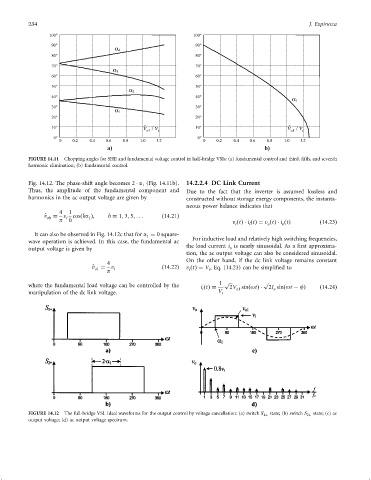
FIGURE 14.11 Chopping angles for SHE and fundamental voltage control in half-bridge VSIs: (a) fundamental control and third, ®fth, and seventh
harmonic elimination; (b) fundamental control.
Fig. 14.12. The phase-shift angle becomes 2 a (Fig. 14.11b). 14.2.2.4 DC Link Current
1
Thus, the amplitude of the fundamental component and Due to the fact that the inverter is assumed lossless and
harmonics in the ac output voltage are given by constructed without storage energy components, the instanta-
neous power balance indicates that
4 1
^ v oh ¼ v i cosðha Þ; h ¼ 1; 3; 5; ... ð14:21Þ
1
p h v ðtÞ i ðtÞ¼ v ðtÞ i ðtÞ ð14:23Þ
o
o
i
i
It can also be observed in Fig. 14.12c that for a ¼ 0 square-
1
wave operation is achieved. In this case, the fundamental ac For inductive load and relatively high switching frequencies,
the load current i is nearly sinusoidal. As a ®rst approxima-
output voltage is given by o
tion, the ac output voltage can also be considered sinusoidal.
On the other hand, if the dc link voltage remains constant
4
^ v ¼ v i ð14:22Þ v ðtÞ¼ V , Eq. (14.23) can be simpli®ed to
o1
i
i
p
1 p p
where the fundamental load voltage can be controlled by the i ðtÞ¼ 2V sinðotÞ 2I sinðot ÿ fÞ ð14:24Þ
o
o1
i
manipulation of the dc link voltage. V i
FIGURE 14.12 The full-bridge VSI. Ideal waveforms for the output control by voltage cancellation: (a) switch S 1þ state; (b) switch S 2þ state; (c) ac
output voltage; (d) ac output voltage spectrum.