
Page 248 - Rashid, Power Electronics Handbook
P. 248
14 Inverters 237
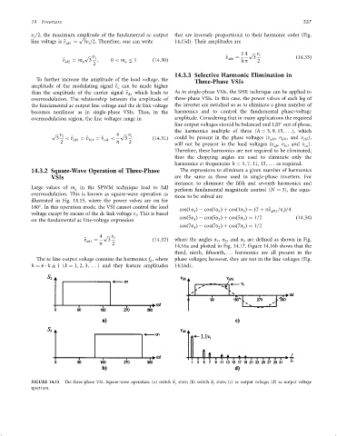
v =2, the maximum amplitude of the fundamental ac output that are inversely proportional to their harmonic order (Fig.
i
p
line voltage is ^ v ab1 ¼ 3v =2. Therefore, one can write 14.15d). Their amplitudes are
i
1 4 p v
p v i ^ v ¼ 3 i ð14:33Þ
^ v ab1 ¼ m a 3 ; 0 < m 1 ð14:30Þ abh h p 2
a
2
14.3.3 Selective Harmonic Elimination in
To further increase the amplitude of the load voltage, the Three-Phase VSIs
amplitude of the modulating signal ^ v can be made higher
c
than the amplitude of the carrier signal ^ v , which leads to As in single-phase VSIs, the SHE technique can be applied to
D
overmodulation. The relationship between the amplitude of three-phase VSIs. In this case, the power valves of each leg of
the fundamental ac output line voltage and the dc link voltage the inverter are switched so as to eliminate a given number of
becomes nonlinear as in single-phase VSIs. Thus, in the harmonics and to control the fundamental phase-voltage
overmodulation region, the line voltages range in amplitude. Considering that in many applications the required
line output voltages should be balanced and 120 out of phase,
the harmonics multiple of three (h ¼ 3; 9; 15; ...), which
p v i 4 p v i
3 < ^ v ab1 ¼ ^ v bc1 ¼ ^ v ca1 < 3 ð14:31Þ could be present in the phase voltages (v , v , and v ),
aN
bN
cN
2 p 2
will not be present in the load voltages (v , v , and v ).
ab
bc
ca
Therefore, these harmonics are not required to be eliminated,
thus the chopping angles are used to eliminate only the
harmonics at frequencies h ¼ 5; 7; 11; 13; .. . as required.
14.3.2 Square-Wave Operation of Three-Phase The expressions to eliminate a given number of harmonics
VSIs are the same as those used in single-phase inverters. For
instance, to eliminate the ®fth and seventh harmonics and
Large values of m in the SPWM technique lead to full perform fundamental magnitude control (N ¼ 3), the equa-
a
overmodulation. This is known as square-wave operation as
tions to be solved are
illustrated in Fig. 14.15, where the power valves are on for
180 . In this operation mode, the VSI cannot control the load
cosð1a Þÿ cosð1a Þþ cosð1a Þ¼ð2 þ p^ v aN1 =v Þ=4
2
3
1
i
voltage except by means of the dc link voltage v . This is based
i
2
1
on the fundamental ac line-voltage expression cosð5a Þÿ cosð5a Þþ cosð5a Þ¼ 1=2 ð14:34Þ
3
cosð7a Þÿ cosð7a Þþ cosð7a Þ¼ 1=2
2
3
1
4 p v i
^ v ¼ 3 ð14:32Þ where the angles a , a , and a are de®ned as shown in Fig.
ab1 p 2 1 2 3
14.16a and plotted in Fig. 14.17. Figure 14.16b shows that the
third, ninth, ®fteenth, ... harmonics are all present in the
The ac line output voltage contains the harmonics f , where phase voltages; however, they are not in the line voltages (Fig.
h
h ¼ 6 k 1(k ¼ 1; 2; 3; ... ) and they feature amplitudes 14.16d).
FIGURE 14.15 The three-phase VSI. Square-wave operation: (a) switch S 1 state; (b) switch S 3 state; (c) ac output voltage; (d) ac output voltage
spectrum.