
Page 253 - Rashid, Power Electronics Handbook
P. 253
242 J. Espinoza
TABLE 14.4 Valid switch states for a three-phase CSI
State State # i oa i ob i oc Space Vector
S 1 and S 2 are on and S 3 , S 4 , S 5 , and S 6 are off 1 i i 0 ÿi i I 1 ¼ 1 þ j0:577
S 2 and S 3 are on and S 4 , S 5 , S 6 , and S 1 are off 2 0 i i ÿi i I 2 ¼ j1:155
S 3 and S 4 are on and S 5 , S 6 , S 1 , and S 2 are off 3 ÿi i i i 0 I 3 ¼ÿ1 þ j0:577
S 4 and S 5 are on and S 6 , S 1 , S 2 , and S 3 are off 4 ÿi i 0 i i I 4 ¼ÿ1 ÿ j0:577
S 5 and S 6 are on and S 1 , S 2 , S 3 , and S 4 are off 5 0 ÿi i i i I 5 ¼ÿj1:155
S 6 and S 1 are on and S 2 , S 3 , S 4 , and S 5 are off 6 i i ÿi i 0 I 6 ¼ 1 ÿ j0:577
S 1 and S 4 are on and S 2 , S 3 , S 5 , and S 6 are off 7 0 0 0 I 7 ¼ 0
S 3 and S 6 are on and S 1 , S 2 , S 4 , and S 5 are off 8 0 0 0 I 8 ¼ 0
S 5 and S 2 are on and S 6 , S 1 , S 3 , and S 4 are off 9 0 0 0 I 9 ¼ 0
should be closed at any time; and (b) the dc bus is of the S and S , switches S and S , or switches S and S . The
3
6
1
4
2
5
current-source type and thus it cannot be opened; therefore, remaining states (1 to 6 in Table 14.4) produce nonzero ac
there must be at least one top switch (1, 3, or 5) and one output line currents. In order to generate a given set of ac line
bottom switch (4, 6, or 2) closed at all times. Note that both current waveforms, the inverter must move from one state to
constraints can be summarized by stating that at any time, another. Thus, the resulting line currents consist of discrete
only one top switch and one bottom switch must be closed. values of current, which are i , 0, and ÿi . The selection of the
i i
There are nine valid states in three-phase CSIs. The states 7, states in order to generate the given waveforms is done by the
8, and 9 (Table 14.4) produce zero ac line currents. In this modulating technique that should ensure the use of only the
case, the dc link current freewheels through either the switches valid states.
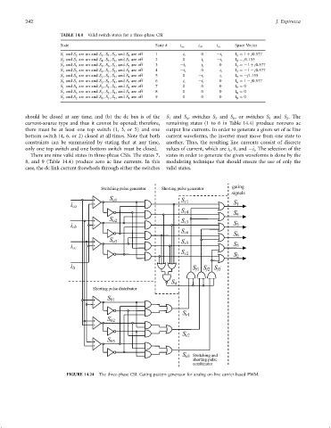
FIGURE 14.24 The three-phase CSI. Gating pattern generator for analog on-line carrier-based PWM.